In auto trigger mode the trigger source is selected by the ADTS bits in the ADCSRB register.
See Table 21-6 on page 249.
• Bit 4– ADIF: ADC Interrupt Flag
Set by hardware as soon as a conversion is complete and the Data register are updated with the
conversion result.
Cleared by hardware when executing the corresponding interrupt handling vector.
Alternatively, ADIF can be cleared by writing it to logical one.
• Bit 3– ADIE: ADC Interrupt Enable Bit
Set this bit to activate the ADC end of conversion interrupt.
Clear it to disable the ADC end of conversion interrupt.
• Bit 2, 1, 0– ADPS2, ADPS1, ADPS0: ADC Prescaler Selection Bits
These 3 bits determine the division factor between the system clock frequency and input clock of
the ADC.
The different setting are shown in Table 21-5.
Table 21-5. ADC Prescaler Selection
ADPS2
ADPS1
ADPS0
Division Factor
0
0
0
0
1
1
1
1
0
0
1
1
0
0
1
1
0
1
0
1
0
1
0
1
2
2
4
8
16
32
64
128
21.8.3
ADC Control and Status Register B– ADCSRB
Bit
7
6
-
5
-
4
ADASCR
R/W
3
ADTS3
R/W
0
2
ADTS2
R/W
0
1
ADTS1
R/W
0
0
ADTS0
R/W
0
ADHSM
ADCSRB
Read/Write
Initial Value
-
-
-
0
0
0
0
• Bit 7 – ADHSM: ADC High Speed Mode
Writing this bit to one enables the ADC High Speed mode. Set this bit if you wish to convert with
an ADC clock frequency higher than 200KHz.
• Bit 4– ADASCR: Analog to Digital Conversion on Amplified Channel Start Conversion
Request Bit (AT90PWM2/3 only - NA on AT90PWM2B/3B)
Set this to request a conversion on an amplified channel.
Cleared by hardware as soon as the Analog to Digital Conversion is started.
Alternatively, this bit can be cleared by writing it to logical zero.
In order to start a conversion on an amplified channel with the AT90PWM2B/3B, use the ADCS
bit in ADCSRA register.
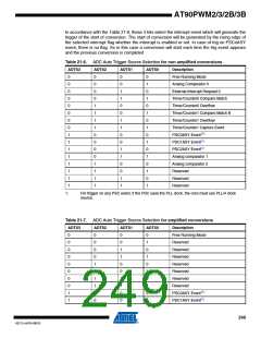
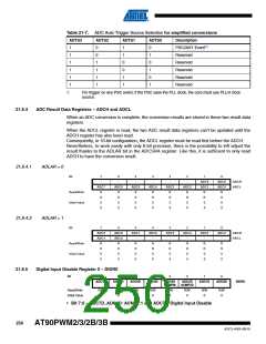
• Bit 3, 2, 1, 0– ADTS3:ADTS0: ADC Auto Trigger Source Selection Bits
These bits are only necessary in case the ADC works in auto trigger mode. It means if ADATE
bit in ADCSRA register is set.
248
AT90PWM2/3/2B/3B
4317J–AVR–08/10

 ATMEL [ ATMEL ]