AT90PWM2/3/2B/3B
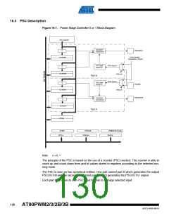
16. Power Stage Controller – (PSC0, PSC1 & PSC2)
The Power Stage Controller is a high performance waveform controller.
16.1 Features
• PWM waveform generation function (2 complementary programmable outputs)
• Dead time control
• Standard mode up to 12 bit resolution
• Frequency Resolution Enhancement Mode (12 + 4 bits)
• Frequency up to 64 Mhz
• Conditional Waveform on External Events (Zero Crossing, Current Sensing ...)
• All on chip PSC synchronization
• ADC synchronization
• Overload protection function
• Abnormality protection function, emergency input to force all outputs to high impedance or in
inactive state (fuse configurable)
• Center aligned and edge aligned modes synchronization
• Fast emergency stop by hardware
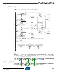
16.2 Overview
Many register and bit references in this section are written in general form.
•
A lower case “n” replaces the PSC number, in this case 0, 1 or 2. However, when using the
register or bit defines in a program, the precise form must be used, i.e., PSOC1 for
accessing PSC 0 Synchro and Output Configuration register and so on.
•
A lower case “x” replaces the PSC part , in this case A or B. However, when using the
register or bit defines in a program, the precise form must be used, i.e., PFRCnA for
accessing PSC n Fault/Retrigger n A Control register and so on.
The purpose of a Power Stage Controller (PSC) is to control power modules on a board. It has
two outputs on PSC0 and PSC1 and four outputs on PSC2.
These outputs can be used in various ways:
•
•
•
“Two Ouputs” to drive a half bridge (lighting, DC motor ...)
“One Output” to drive single power transistor (DC/DC converter, PFC, DC motor ...)
“Four Outputs” in the case of PSC2 to drive a full bridge (lighting, DC motor ...)
Each PSC has two inputs the purpose of which is to provide means to act directly on the gener-
ated waveforms:
•
•
•
•
Current sensing regulation
Zero crossing retriggering
Demagnetization retriggering
Fault input
The PSC can be chained and synchronized to provide a configuration to drive three half bridges.
Thanks to this feature it is possible to generate a three phase waveforms for applications such
as Asynchronous or BLDC motor drive.
129
4317J–AVR–08/10

 ATMEL [ ATMEL ]