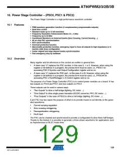
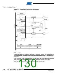
16.3 PSC Description
Figure 16-1. Power Stage Controller 0 or 1 Block Diagram
PSC Counter
Waveform
Generator B
PSCOUTn1
=
( From Analog
Comparator n Ouput )
OCRnRB
PSC Input
Module B
PSCn Input B
=
OCRnSB
PISELnB
Part B
PSCn Input A
PSC Input
Module A
=
PSCINn
OCRnRA
PISELnA
PSCOUTn0
Waveform
Generator A
=
OCRnSA
Part A
PICRn
PCNFn
PCTLn
PFRCnB
PFRCnA
POM2(PSC2 only)
PSOCn
Note:
n = 0, 1
The principle of the PSC is based on the use of a counter (PSC counter). This counter is able to
count up and count down from and to values stored in registers according to the selected run-
ning mode.
The PSC is seen as two symetrical entities. One part named part A which generates the output
PSCOUTn0 and the second one named part B which generates the PSCOUTn1 output.
Each part A or B has its own PSC Input Module to manage selected input.
130
AT90PWM2/3/2B/3B
4317J–AVR–08/10

 ATMEL [ ATMEL ]