AT90PWM2/3/2B/3B
16.3.1
PSC2 Distinctive Feature
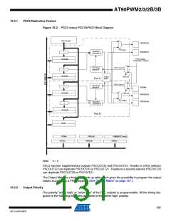
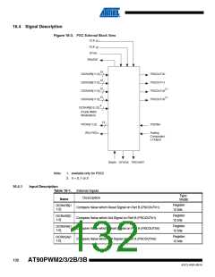
Figure 16-2. PSC2 versus PSC1&PSC0 Block Diagram
PSC Counter
PSCOUTn3
POS23
Waveform
PSCOUTn1
=
Generator B
( From Analog
Comparator n Ouput )
OCRnRB
PSC Input
Module B
PSCn Input B
=
OCRnSB
Output
Matrix
PISELnB
Part A
PSCn Input A
PSC Input
Module A
=
PSCINn
OCRnRA
PISELnA
PSCOUTn2
POS22
PSCOUTn0
Waveform
=
Generator A
OCRnSA
Part B
PICRn
PCNFn
PCTLn
PFRCnB
PFRCnA
POM2(PSC2 only)
PSOCn
Note:
n = 2
PSC2 has two supplementary outputs PSCOUT22 and PSCOUT23. Thanks to a first selector
PSCOUT22 can duplicate PSCOUT20 or PSCOUT21. Thanks to a second selector PSCOUT23
can duplicate PSCOUT20 or PSCOUT21.
The Output Matrix is a kind of 2*2 look up table which gives the possibility to program the output
values according to a PSC sequence (See “Output Matrix” on page 157.)
16.3.2
Output Polarity
The polarity “active high” or “active low” of the PSC outputs is programmable. All the timing dia-
grams in the following examples are given in the “active high” polarity.
131
4317J–AVR–08/10

 ATMEL [ ATMEL ]