Set to deassert the UVCON pin in order to enable the VBUS power supply generation. This bit
shall be used when the controller is in the Host mode.
Cleared by hardware immediately after the set.
Bit
7
1
6
5
4
-
3
-
2
1
VALUE
R/W
0
0
PAGE
OTGTCON
Read/Write
Initial Value
R
1
R/W
0
R/W
0
R
0
R
0
R/W
0
R/W
0
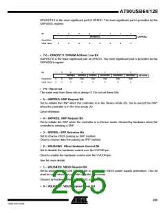
• 7 – Reserved
This bit is reserved and always set.
• 6-5 – PAGE: Timer page access Bit
Set/clear to access a special timer register. See Section 21.10, page 260 for more details.
• 4-3 - Reserved
The value read from these bits is always 0. Do not set these bits.
• 2-0 – VALUE: Value Bit
Set to initialize the new value of the timer. See Section 21.10, page 260 for more details.
Bit
7
-
6
-
5
STOE
R/W
0
4
HNPERRE
R/W
3
ROLEEXE
R/W
2
BCERRE
R/W
1
VBERRE
R/W
0
SRPE
R/W
0
OTGIEN
Read/Write
Initial Value
R
0
R
0
0
0
0
0
• 7-6 - Reserved
The value read from these bits is always 0. Do not set these bits.
• 5 – STOE: Suspend Time-out Error Interrupt Enable Bit
Set to enable the STOI interrupt. Clear to disable the STOI interrupt.
• 4 – HNPERRE: HNP Error Interrupt Enable Bit
Set to enable the HNPERRI interrupt. Clear to disable the HNPERRI interrupt.
• 3 – ROLEEXE: Role Exchange Interrupt Enable Bit
Set to enable the ROLEEXI interrupt. Clear to disable the ROLEEXI interrupt.
• 2 – BCERRE: B-Connection Error Interrupt Enable Bit
Set to enable the BCERRI interrupt. Clear to disable the BCERRI interrupt.
• 1 – VBERRE: VBus Error Interrupt Enable Bit
Set to enable the VBERRI interrupt. Clear to disable the VBERRI interrupt.
• 0 – SRPE: SRP Interrupt Enable Bit
Set to enable the SRPI interrupt. Clear to disable the SRPI interrupt.
266
AT90USB64/128
7593A–AVR–02/06

 ATMEL [ ATMEL ]