AT90USB64/128
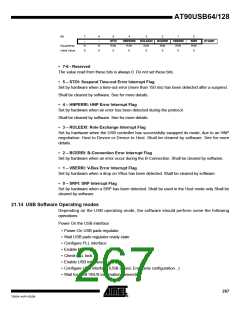
• 3-1 – Reserved
The value read from these bits is always 0. Do not set these bits.
• 0 – UVREGE: USB pad regulator Enable
Set to enable the USB pad regulator. Clear to disable the USB pad regulator.
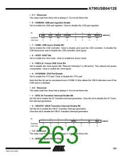
Bit
7
USBE
R/W
0
6
HOST
R/W
0
5
FRZCLK
R/W
4
OTGPADE
R/W
3
-
2
-
1
IDTE
R/W
0
0
VBUSTE
R/W
USBCON
Read/Write
Initial Value
R
0
R
0
1
0
0
• 7 – USBE: USB macro Enable Bit
Set to enable the USB controller. Clear to disable and reset the USB controller, to disable the
USB transceiver and to disable the USB controller clock inputs.
• 6 – HOST: HOST Bit
Set to enable the Host mode. Clear to enable the device mode.
• 5 – FRZCLK: Freeze USB Clock Bit
Set to disable the clock inputs (the ”Resume Detection” is still active). This reduces the power
consumption. Clear to enable the clock inputs.
• 4 – OTGPADE: OTG Pad Enable
Set to enable the OTG pad. Clear to disable the OTG pad.
Note that this bit can be set/cleared even if USBE=0 (this allows the VBUS detection even if the
USB macro is disable).
• 3-2 – Reserved
The value read from these bits is always 0. Do not set these bits.
• 1 – IDTE: ID Transition Interrupt Enable Bit
Set this bit to enable the ID Transition interrupt generation. Clear this bit to disable the ID Transi-
tion interrupt generation.
• 0 – VBUSTE: VBUS Transition Interrupt Enable Bit
Set this bit to enable the VBUS Transition interrupt generation.
Clear this bit to disable the VBUS Transition interrupt generation.
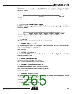
Bit
7
-
6
-
5
-
4
-
3
2
1
ID
R
1
0
VBUS
R
SPEED
USBSTA
Read/Write
Initial Value
R
0
R
0
R
0
R
0
R
1
R
0
0
• 7-4 - Reserved
The value read from these bits is always 0. Do not set these bits.
• 3 – SPEED: Speed Status Flag
263
7593A–AVR–02/06

 ATMEL [ ATMEL ]