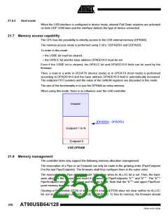
21.12 ID detection
The ID pin transition is detected thanks to the following architecture:
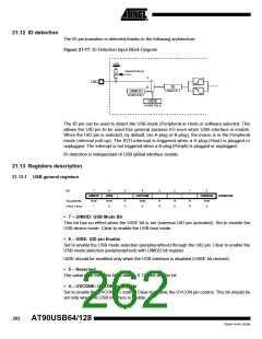
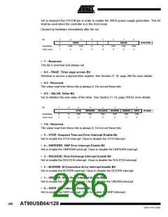
Figure 21-17. ID Detection Input Block Diagram
VDD
Internal Pull Up
1
UID
ID
USBSTA.1
0
UIMOD
UHWCON.7
UIDE
UHWCON.6
The ID pin can be used to detect the USB mode (Peripheral or Host) or software selected. This
allows the UID pin to be used has general purpose I/O even when USB interface is enable.
When the UID pin is selected, by default, (no A-plug or B-plug), the macro is in the Peripheral
mode (internal pull-up). The IDTI interrupt is triggered when a A-plug (Host) is plugged or
unplugged. The interrupt is not triggered when a B-plug (Periph) is plugged or unplugged.
ID detection is independant of USB global interface enable.
21.13 Registers description
21.13.1 USB general registers
Bit
7
UIMOD
R/W
1
6
UIDE
R/W
0
5
4
UVCONE
R/W
3
2
1
0
UVREGE
R/W
UHWCON
Read/Write
Initial Value
R
0
R
0
R
0
R
0
0
0
• 7 – UIMOD: USB Mode Bit
This bit has no effect when the UIDE bit is set (external UID pin activated). Set to enable the
USB device mode. Clear to enable the USB host mode
• 6 – UIDE: UID pin Enable
Set to enable the USB mode selection (peripheral/host) through the UID pin. Clear to enable the
USB mode selection (peripheral/host) with UIMOD bit register.
UIDE should be modified only when the USB interface is disabled (USBE bit cleared).
• 5 – Reserved
The value read from this bit is always 0. Do not set this bit.
• 4 – UVCONE: UVCON pin Enable
Set to enable the UVCON pin control. Clear to disable the UVCON pin control. This bit should be
set only when the USB interface is enable.
262
AT90USB64/128
7593A–AVR–02/06

 ATMEL [ ATMEL ]