This should be read only when the USB controller operates in host mode, in device mode the
value read from this bit is underterminate.
Set by hardware when the controller is in FULL-SPEED mode. Cleared by hardware when the
controller is in LOW-SPEED mode.
• 2 – Reserved
The value read from this bit is always 0. Do not set this bit.
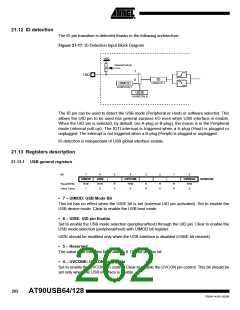
• 1 – ID: IUD pin Flag
The value read from this bit indicates the state of the UID pin.
• 0 – VBUS: VBus Flag
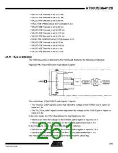
The value read from this bit indicates the state of the UVBUS pin. This bit can be used in device
mode to monitor the USB bus connection state of the appication. See Section 21.11, page 261
for more details.
Bit
7
-
6
-
5
-
4
-
3
-
2
-
1
0
VBUSTI
R/W
0
IDTI
R/W
0
USBINT
Read/Write
Initial Value
R
0
R
0
R
0
R
0
R
0
R
0
7-2 - Reserved
The value read from these bits is always 0. Do not set these bits.
1 – IDTI: D Transition Interrupt Flag
Set by hardware when a transition (high to low, low to high) has been detected on the UID pin.
Shall be cleared by software.
• 0 – VBUSTI: IVBUS Transition Interrupt Flag
Set by hardware when a transition (high to low, low to high) has been detected on the VBUS
pad.
Shall be cleared by software.
Bit
7
DPACC
R/W
0
6
5
4
3
2
0
1
0
0
-
-
-
-
DPADD10:8
UDPADDH
Read/Write
Initial Value
0
0
0
0
0
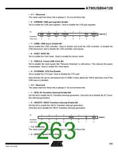
• 7 – DPACC: DPRAM Direct Access Bit
Set this bit to directly read the content the Dual-Port RAM (DPR) data through the UEDATX or
UPDATX registers. See Section 21.7, page 258 for more details.
Clear this bit for normal operation and access the DPR through the endpoint FIFO.
• 6-3 – Reserved
The value read from these bits is always 0. Do not set these bits.
• 2- 0 – DPADD10:8: DPRAM Address High Bit
264
AT90USB64/128
7593A–AVR–02/06

 ATMEL [ ATMEL ]