AT90USB64/128
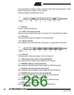
Bit
7
-
6
-
5
STOI
R/W
0
4
HNPERRI
R/W
3
ROLEEXI
R/W
2
BCERRI
R/W
0
1
VBERRI
R/W
0
0
SRPI
R/W
0
OTGINT
Read/Write
Initial Value
R
0
R
0
0
0
• 7-6 - Reserved
The value read from these bits is always 0. Do not set these bits.
• 5 – STOI: Suspend Time-out Error Interrupt Flag
Set by hardware when a time-out error (more than 150 ms) has been detected after a suspend.
Shall be cleared by software. See for more details.
• 4 – HNPERRI: HNP Error Interrupt Flag
Set by hardware when an error has been detected during the protocol.
Shall be cleared by software. See for more details.
• 3 – ROLEEXI: Role Exchange Interrupt Flag
Set by hardware when the USB controller has successfully swapped its mode, due to an HNP
negotiation: Host to Device or Device to Host. Shall be cleared by software. See for more
details.
• 2 – BCERRI: B-Connection Error Interrupt Flag
Set by hardware when an error occur during the B-Connection. Shall be cleared by software.
• 1 – VBERRI: V-Bus Error Interrupt Flag
Set by hardware when a drop on VBus has been detected. Shall be cleared by software.
• 0 – SRPI: SRP Interrupt Flag
Set by hardware when a SRP has been detected. Shall be used in the Host mode only Shall be
cleared by software.
21.14 USB Software Operating modes
Depending on the USB operating mode, the software should perform some the following
operations:
Power On the USB interface
• Power-On USB pads regulator
• Wait USB pads regulator ready state
• Configure PLL interface
• Enable PLL
• Check PLL lock
• Enable USB interface
• Configure USB interface (USB speed, Endpoints configuration...)
• Wait for USB VBUS information connection
267
7593A–AVR–02/06

 ATMEL [ ATMEL ]