AT90USB64/128
22. USB Device Operating modes
22.1 Introduction
The USB device controller supports full speed and low speed data transfers. In addition to the
default control endpoint, it provides six other endpoints, which can be configured in control, bulk,
interrupt or isochronous modes:
• Endpoint 0:programmable size FIFO up to 64 bytes, default control endpoint
• Endpoints 1 programmable size FIFO up to 256 bytes in ping-pong mode.
• Endpoints 2 to 6: programmable size FIFO up to 64 bytes in ping-pong mode.
The controller starts in the “idle” mode. In this mode, the pad consumption is reduced to the
minimum.
22.2 Power-on and reset
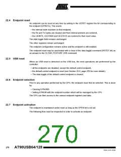
The next diagram explains the USB device controller main states on power-on:
Figure 22-1. USB device controller states after reset
<any
other
state>
USBE=0
USBE=0
Idle
USBE=1
UID=1
Reset
HW
RESET
The reset state of the Device controller is:
• the macro clock is stopped in order to minimize the power consumption (FRZCLK set),
• the USB device controller internal state is reset (all the registers are reset to their default
value. Note that DETACH is set.)
• the endpoint banks are reset
• the D+ or D- pull up are not activated (mode Detach)
The D+ or D- pull-up will be activated as soon as the DETACH bit is cleared and VBUS is
present.
The macro is in the ‘Idle’ state after reset with a minimum power consumption and does not
need to have the PLL activated to enter in this state.
The USB device controller can at any time be reset by clearing USBE (disable USB interface).
22.3 Speed identification on startup
The usb bus reset is managed by the hardware. At the connection, the host makes a reset that
can be:
At the end of the reset process (full speed or low speed mode), the end of reset interrupt
(EORSTI) is generated. Then the CPU can read the SPEED1 bit to know the speed mode of the
device.
269
7593A–AVR–02/06

 ATMEL [ ATMEL ]