AT90USB64/128
clear ALLOC. Then, the “ki+1” Pipe/Endpoint memory automatically “slides” down. Note that the
“ki+2” and upper Pipe/Endpoint memory does not slide.
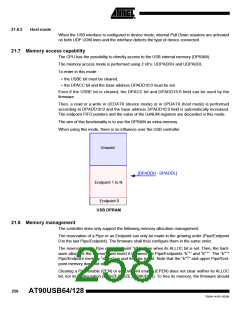
The following figure illustrates the allocation and reorganization of the USB memory in a typical
example:
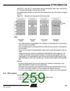
Table 21-1. Allocation and reorganization USB memory flow
Free memory
5
Free memory
Free memory
5
Free memory
5
4
5
4
Conflict
4
3
Lost memory
4
EPEN=0
(ALLOC=1)
3 (bigger size)
2
2
2
2
1
0
1
0
1
0
1
0
EPEN=1
ALLOC=1
Pipe/Endpoints
activation
Pipe/Endpoint
Disable
Free its memory
(ALLOC=0)
Pipe/Endpoint
Activatation
• First, Pipe/Endpoint 0 to Pipe/Endpoint 5 are configured, in the growing order. The memory of
each is reserved in the DPRAM.
• Then, the Pipe/Endpoint 3 is disabled (EPEN=0), but its memory reservation is internally kept
by the controller.
• Its ALLOC bit is cleared: the Pipe/Endpoint 4 “slides” down, but the Pipe/Endpoint 5 does not
“slide”.
• Finally, if the firmware chooses to reconfigure the Pipe/Endpoint 3, with a bigger size. The
controller reserved the memory after the endpoint 2 memory and automatically “slide” the
Pipe/Endpoint 4. The Pipe/Endpoint 5 does not move and a memory conflict appear, in that
both Pipe/Endpoint 4 and 5 use a common area. The data of those endpoints are potentially
lost.
Note that:
• the data of Pipe/Endpoint 0 are never lost whatever the activation or deactivation of the
higher Pipe/Endpoint. Its data is lost if it is deactivated.
• Deactivate and reactivate the same Pipe/Endpoint with the same parameters does not lead
to a “slide” of the higher endpoints. For those endpoints, the data are preserved.
• CFGOK is set by hardware even in the case that there is a “conflict” in the memory allocation.
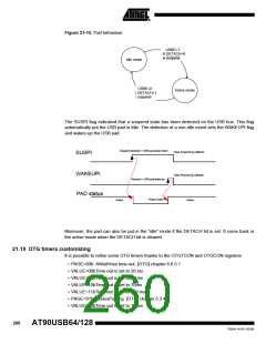
21.9 PAD suspend
The next figures illustrates the pad behaviour:
• In the “idle” mode, the pad is put in low power consumption mode.
• In the “active” mode, the pad is working.
259
7593A–AVR–02/06

 ATMEL [ ATMEL ]