AT90USB64/128
• VALUE=01bTime-out is set to 23 ms
• VALUE=10bTime-out is set to 31 ms
• VALUE=11bTime-out is set to 40 ms
• PAGE=10b: PdTmOutCnt. [OTG] chapter 5.3.2
• VALUE=00bTime-out is set to 93 ms
• VALUE=01bTime-out is set to 105 ms
• VALUE=10bTime-out is set to 118 ms
• VALUE=11bTime-out is set to 131 ms
• PAGE=11b: SRPDetTmOut. [OTG] chapter 5.3.3
• VALUE=00bTime-out is set to 10 us
• VALUE=01bTime-out is set to 100 us
• VALUE=10bTime-out is set to 1 ms
• VALUE=11bTime-out is set to 11 ms
21.11 Plug-in detection
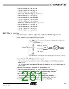
The USB connection is detected by the VBUS pad, thanks to the following architecture:
Figure 21-16. Plug-in Detection Input Block Diagram
VDD
VBus_pulsing
Session_valid
UVBUS
Logic
VBUS
USBSTA.0
VBUSTI
USBINT.0
Va_Vbus_valid
VBus_discharge
VSS
Pad logic
The control logic of the UVBUS pad outputs 2 signals:
• The “session_valid” signal is active high when the voltage on the UVBUS pad is higher or
equal to 1.4V.
• The “Va_Vbus_valid” signal is active high when the voltage on the UVBUS pad is higher or
equal to 4.4V.
In the Host mode, the VBUS flag follows the next hysteresis rule:
• VBUS is set when the voltage on the UVBUS pad is higher or equal to 4.4 V.
• VBUS is cleared when the voltage on the UVBUS pad is lower than 1.4 V.
In the Peripheral mode, the VBUS flag follows the next rule:
• VBUS is set when the voltage on the UVBUS pad is higher or equal to 1.4 V.
• VBUS is cleared when the voltage on the UVBUS pad is lower than 1.4 V.
The VBUSTI interrupt is triggered at each transition of the VBUS flag.
261
7593A–AVR–02/06

 ATMEL [ ATMEL ]