Bit
Bit Number Mnemonic Description
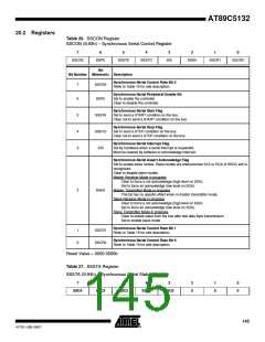
Synchronous Serial Status Code Bits 0 to 4
Refer to Table 20 to Table 20-6 for status description.
7:3
2:0
SSC4:0
0
Always 0.
Reset Value = F8h
Table 28. SSDAT Register
SSDAT (S:95h) – Synchronous Serial Data Register
7
6
5
4
3
2
1
0
SSD7
SSD6
SSD5
SSD4
SSD3
SSD2
SSD1
SSD0
Bit
Bit Number Mnemonic Description
7:1
0
SSD7:1
SSD0
Synchronous Serial Address bits 7 to 1 or Synchronous Serial Data Bits 7 to 1
Synchronous Serial Address bit 0 (R/W) or Synchronous Serial Data Bit 0
Reset Value = 1111 1111b
Table 29. SSADR Register
SSADR (S:96h) – Synchronous Serial Address Register
7
6
5
4
3
2
1
0
SSA7
SSA6
SSA5
SSA4
SSA3
SSA2
SSA1
SSGC
Bit
Bit Number Mnemonic Description
7:1
0
SSA7:1
SSGC
Synchronous Serial Slave Address Bits 7 to 1
Synchronous Serial General Call Bit
Set to enable the general call address recognition.
Clear to disable the general call address recognition.
Reset Value = 1111 1110b
146
AT89C5132
4173E–USB–09/07

 ATMEL [ ATMEL ]