AT89C5132
20.2 Registers
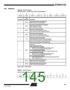
Table 26. SSCON Register
SSCON (S:93h) – Synchronous Serial Control Register
7
6
5
4
3
2
1
0
SSCR2
SSPE
SSSTA
SSSTO
SSI
SSAA
SSCR1
SSCR0
Bit
Bit Number Mnemonic Description
Synchronous Serial Control Rate Bit 2
Refer to Table 19 for rate description.
7
6
SSCR2
SSPE
Synchronous Serial Peripheral Enable Bit
Set to enable the controller.
Clear to disable the controller.
Synchronous Serial Start Flag
Set to send a START condition on the bus.
Clear not to send a START condition on the bus.
5
4
3
SSSTA
SSSTO
SSI
Synchronous Serial Stop Flag
Set to send a STOP condition on the bus.
Clear not to send a STOP condition on the bus.
Synchronous Serial Interrupt Flag
Set by hardware when a serial interrupt is requested.
Must be cleared by software to acknowledge interrupt.
Synchronous Serial Assert Acknowledge Flag
Set to enable slave modes. Slave modes are entered when SLA or GCA (if SSGC set) is
recognized.
Clear to disable slave modes.
Master Receiver Mode in progress
Clear to force a not acknowledge (high level on SDA).
Set to force an acknowledge (low level on SDA).
Master Transmitter Mode in progress
2
SSAA
This bit has no specific effect when in master transmitter mode.
Slave Receiver Mode in progress
Clear to force a not acknowledge (high level on SDA).
Set to force an acknowledge (low level on SDA).
Slave Transmitter Mode in progress
Clear to isolate slave from the bus after last data Byte transmission.
Set to enable slave mode.
Synchronous Serial Control Rate Bit 1
Refer to Table 19 for rate description.
1
0
SSCR1
SSCR0
Synchronous Serial Control Rate Bit 0
Refer to Table 19 for rate description.
Reset Value = 0000 0000b
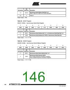
Table 27. SSSTA Register
SSSTA (S:94h) – Synchronous Serial Status Register
7
6
5
4
3
2
0
1
0
0
0
SSC4
SSC3
SSC2
SSC1
SSC0
145
4173E–USB–09/07

 ATMEL [ ATMEL ]