AT89C5132
18. Serial I/O Port
The serial I/O port in the AT89C5132 provides both synchronous and asynchronous communi-
cation modes. It operates as a Synchronous Receiver and Transmitter in one single mode
(Mode 0) and operates as an Universal Asynchronous Receiver and Transmitter (UART) in three
full-duplex modes (modes 1, 2 and 3). Asynchronous modes support framing error detection and
multiprocessor communication with automatic address recognition.
18.1 Mode Selection
SM0 and SM1 Bits in SCON register (see Figure 91) are used to select a mode among the sin-
gle synchronous and the three asynchronous modes according to Table 89.
Table 89. Serial I/O Port Mode Selection
SM0
SM1
Mode
Description
Baud Rate
Fixed/Variable
Variable
0
0
1
1
0
1
0
1
0
1
2
3
Synchronous Shift Register
8-bit UART
9-bit UART
Fixed
9-bit UART
Variable
18.2 Baud Rate Generator
Depending on the mode and the source selection, the baud rate can be generated from either
the Timer 1 or the Internal Baud Rate Generator. The Timer 1 can be used in Modes 1 and 3
while the Internal Baud Rate Generator can be used in Modes 0, 1
and 3.
The addition of the Internal Baud Rate Generator allows freeing of the Timer 1 for other pur-
poses in the application. It is highly recommended to use the Internal Baud Rate Generator as it
allows higher and more accurate baud rates than Timer 1.
Baud rate formulas depend on the modes selected and are given in the following mode sections.
18.2.1
Timer 1
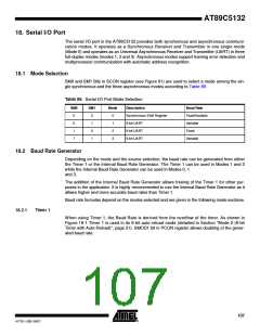
When using Timer 1, the Baud Rate is derived from the overflow of the timer. As shown in
Figure 18-1 Timer 1 is used in its 8-bit auto-reload mode (detailed in Section "Mode 2 (8-bit
Timer with Auto-Reload)", page 51). SMOD1 bit in PCON register allows doubling of the gener-
ated baud rate.
107
4173E–USB–09/07

 ATMEL [ ATMEL ]