AT85C51SND3Bx
Keyboard Interface
The AT85C51SND3Bx implement a keyboard interface allowing the connection of a
4 x n matrix keyboard. It is based on 4 inputs with programmable interrupt capability on
both high or low level. These inputs are available as alternate function of P1.3:0 and
allow exit from idle and power down modes.
Description
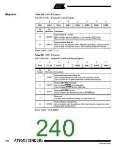
The keyboard interfaces with the C51 core through 2 special function registers: KBCON,
the keyboard control register (see Table 260); and KBSTA, the keyboard control and
status register (see Table 261).
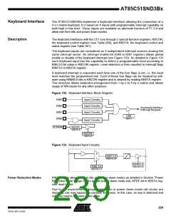
The keyboard inputs are considered as 4 independent interrupt sources sharing the
same interrupt vector. An interrupt enable bit (EKB in IEN1 register) allows global
enable or disable of the keyboard interrupt (see Figure 132). As detailed in Figure 133
each keyboard input has the capability to detect a programmable level according to
KINL3:0 bit value in KBCON register. Level detection is then reported in interrupt flags
KINF3:0 in KBSTA register.
A keyboard interrupt is requested each time one of the four flags is set, i.e. the input
level matches the programmed one. Each of these four flags can be masked by soft-
ware using KINM3:0 bits in KBCON register and is cleared by reading KBSTA register.
This structure allows keyboard arrangement from 1 by n to 4 by n matrix and allows
usage of KIN inputs for any other purposes.
Figure 132. Keyboard Interface Block Diagram
KIN3
KIN2
KIN1
KIN0
Input Circuitry
Input Circuitry
Input Circuitry
Keyboard Interface
Interrupt Request
EKB
IEN1.1
Input Circuitry
DCPWR
KDCPL
KBSTA.5
KDCPE
KBSTA.6
Figure 133. Keyboard Input Circuitry
0
1
KINF3:0
KBSTA.3:0
KINM3:0
KBCON.3:0
KINL3:0
KBCON.7:4
Power Reduction Modes
KIN3:0 inputs allow exit from idle and power-down modes as detailed in Section “Power
Reduction Mode”, page 20. To enable power-down mode exit, KPDE bit in KBSTA reg-
ister must be set.
Due to the asynchronous keypad detection in power down mode (all clocks are
stopped), exit may happen on parasitic key press. In this case, no key is detected and
software returns to power down again.
239
7632A–MP3–03/06

 ATMEL [ ATMEL ]