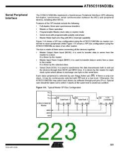
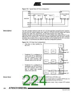
Figure 115. Typical Slave SPI Bus Configuration
SSn
SS1
SS
AT85C51SND3B
Slave
SS0
SS
SS
Slave 1
Slave 2
SO
SI SCK
SO
SI SCK
MISO MOSI SCK
MASTER
MISO
MOSI
SCK
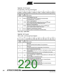
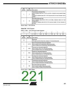
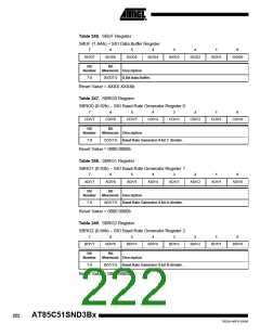
Description
The SPI controller interfaces with the C51 core through three special function registers:
SPCON, the SPI control register (see Table 251); SPSCR, the SPI status and control
register (see Table 252); and SPDAT, the SPI data register (see Table 253).
Data flow transfer can be fully handled by the C51 by writing and reading SPDAT or par-
tially by the C51 and the DFC. The SPI controller implements only one DFC channel,
meaning only reception flow or transmission flow can be handled by the DFC at a time.
The Figure 116 summarizes the different data flow configuration allowed.
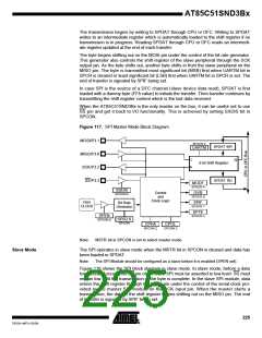
Figure 116. SPI Data Flow Configurations
•
•
•
Data flow is fully handled by
the CPU.
CPU
IN
Per X
Per X
Per X
DFC
DFC
DFC
SPI
OUT
Peripheral X is configured as
source and SPI as destination
of a DFC channel. CPU is still
able to read incoming data
(usually status) at its own rate.
CPU
IN
SPI
OUT
Peripheral X is configured as
destination and SPI as source
of a DFC channel. CPU is still
able to output data (usually
status) at its own rate.
CPU
IN
SPI
OUT
Master Mode
The SPI operates in master mode when the MSTR bit in SPCON is set.
Note:
The SPI Module should be configured as a master before it is enabled (SPEN set). In a
system, the master SPI should be configured before the slave SPI device.
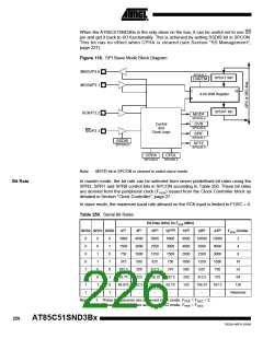
Figure 117 shows the SPI block diagram in master mode. Only a master SPI module
can initiate transmissions.
224
AT85C51SND3Bx
7632A–MP3–03/06

 ATMEL [ ATMEL ]