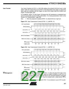
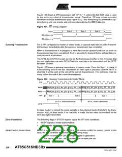
Figure 120 shows a SPI transmission with CPHA = 1, where the first SCK edge is used
by the slave as a start of transmission signal. Therefore, SS may remain asserted
between each byte transmission (see Figure 121). This format may be preferred in sys-
tems having only one master and only one slave driving the MISO data line.
Figure 121. SS Timing Diagram
Byte 1
Byte 2
Byte 3
SI/SO
SS (CPHA = 0)
SS (CPHA = 1)
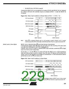
Queuing Transmission
For a SPI configured in master or slave mode, a queued data byte must be transmit-
ted/received immediately after the previous transmission has completed.
When a transmission is in progress a new data can be queued and sent as soon as
transmission has been completed. So it is possible to transmit bytes without latency,
useful in some applications.
The SPTE bit in SPSCR is set as long as the transmission buffer is free. It means that
the user application can write SPDAT with the next data to be transmitted until the SPTE
becomes cleared.
Figure 122 shows a queuing transmission in master mode. Once the Byte 1 is ready, it
is immediately sent on the bus. Meanwhile an other byte is prepared (and the SPTE is
cleared), it will be sent at the end of the current transmission. The next data must be
ready before the end of the current transmission.
Figure 122. Queuing Transmission In Master Mode
SCK
MSB
MSB
B1
B1
MSB
MSB
B1
B1
B6 B5 B4 B3 B2
B6 B5 B4 B3 B2
Byte 3
LSB
LSB
B6 B5 B4 B3 B2
B6 B5 B4 B3 B2
LSB
LSB
MOSI
MISO
Data
Byte 1
Byte 2
BYTE 1 under transmission
BYTE 2 under transmission
SPTE
In slave mode it is almost the same except it is the external master that starts the trans-
mission. Also, in slave mode, if no new data is ready, the last value received will be the
next data byte transmitted.
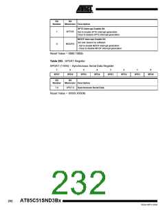
Error Conditions
The following flags in SPSCR register signal the SPI error conditions:
•
•
MODF signals a mode fault condition.
OVR signals an overrun condition.
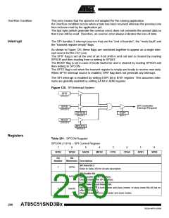
Mode Fault in Master Mode
MODF is set to warn that there may be a multi-master conflict for system control. In this
case, the SPI controller is affected in the following ways:
–
–
a SPI receiver/error CPU interrupt request is generated
the SPEN bit in SPCON is cleared. This disables the SPI
228
AT85C51SND3Bx
7632A–MP3–03/06

 ATMEL [ ATMEL ]