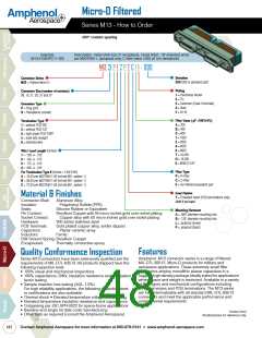
Micro-D Filtered
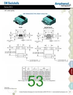
Series M13
Amphenol
Aerospace
.050" contact spacing
C-Filter Specifications
Filter Circuits
C, CLR, LRC
600-1200 1200 -3200 4000-8000 8000-16000
Capacitance (pF) (@ 25 C, 1 kHz and 1.0 VRMS)
Insertion Loss (dB min.)
(per MIL-STD-220)
150-300
300-500
.1 MHz
-
-
-
-
-
-
-
-
-
-
1 MHz
-
-
(@ 25C and no load)
10 MHz
100 MHz
1000 MHz
-
-
2
5
13
33
54
18
40
60
6
12
31
17
38
24
43
25
Working Voltage (VDC) (@ 25 C and sea level)
100
300
Dielectric Withstanding Voltage (VDC)
(@25 C and 50 mA max. charging current)
Insulation Resistance (Gohms)
(@25 C and working voltage)
5
3
Contact Current Rating
(continuous max. DC amperes)
Filter RF Current Rating (amperes)
(max. @ any frequency)
0.3
Pi-Filter Specifications
Filter Circuits
Pi
Capacitance (pF) (@ 25 C, 1 kHz and 1.0 VRMS)
Insertion Loss (dB min.)
(per MIL-STD-220)
150-300
300-500
600-1200
1200-3200 4000-8000 8000-16000
.1 MHz
-
-
-
-
-
-
-
-
-
-
1 MHz
-
3
(@ 25 C and no load)
10 MHz
100 MHz
1000 MHz
-
-
2
5
13
45
60
18
57
60
7
12
42
18
53
26
60
30
Working Voltage (VDC) (@25 C and sea level)
100
300
Dielectric Withstanding Voltage (VDC)
(@25 C and 50 mA max. charging current)
Insulation Resistance (Gohms)
(@25 C and working voltage)
5
3
Contact Current Rating
(Continuous max. DC amperes)
Filter RF Current Rating (amperes)
(max. @ any frequency)
0.3
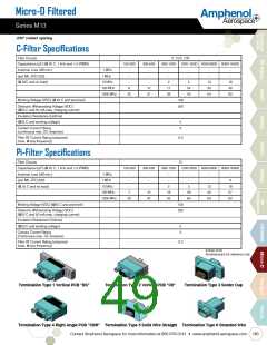
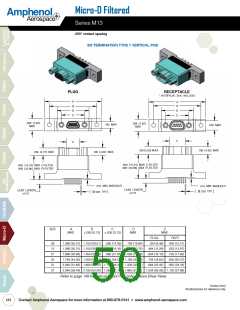
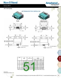
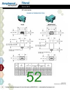
Inches (mm)
All dimensions for reference only
Termination Type 1 vertical PCb "bS"
Termination Type 2 vertical PCb "C6"
Termination Type 3 Solder Cup
Termination Type 4 ꢁight Angle PCb "Cbꢁ" Termination Type 5 Solid wire Straight Termination Type 6 Stranded wire
Contact Amphenol Aerospace for more information at 800-678-0141 • www.amphenol-aerospace.com
183

 AMPHENOL [ Amphenol ]