BCR 47
BCR 46
BCR 45
BCR Bit Number 15
Pattern Match
8
7
0
15
8
7
0
15
7
8
PMR_B4
PMR_B3
Pattern Match RAM Bit Number
24 23 16 15
PMR_B2
PMR_B1
PMR_B0
Comments
RAM Address
39
32 31
8
0
Pattern Enable
bits
0
P3 pointer
P7 pointer
P2 pointer
P1 pointer
P0 pointer
First Address
Second
Address
1
2
P6 pointer
P5 pointer
Data Byte1
P4 pointer
X
Start Pattern
P1
Data Byte 3
Data Byte 2
Data Byte 0
Pattern Control
2+n
J
Data Byte 4n+3 Date Byte 4n+2 Data Byte 4n+1 Data Byte 4n+0 Pattern Control End Pattern P1
Start Pattern
Data Byte 3
Data Byte 2
Data Byte 1
Data Byte 0
Pattern Control
Pk
J+m
63
Data Byte 4m+3 Data Byte 4m+2 Data Byte 4m+1 Data Byte 4m+0 Pattern Control End Pattern Pk
Last Address
7
6
5
4
3
2
1
0
EOP
SKIP
MASK
22206B-51
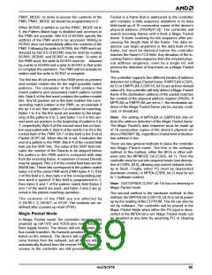
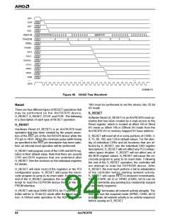
Figure 47. Pattern Match RAM
When the controller detects a Magic Packet frame, it
sets the MPMAT bit (CSR116, bit 5), the MPINT bit
(CSR5, bit 4), and the PME_STATUS bit (PMCSR, bit
15). If the PME_EN or the PME_EN_OVR bits are set,
the PME will be asserted as well. If IENA (CSR0, bit 6)
and MPINTE (CSR5, bit 3) are set to 1, INTA will be as-
serted. Any one of the four LED pins can be pro-
grammed to indicate that a Magic Packet frame has
been received. MPSE (BCR4-7, bit 9) must be set to 1
to enable that function.
mal transmit and receive operations until PG is as-
serted or MPEN is cleared. Once both of these events
has occurred, indicating that the system has detected
the Magic Packet and is awake, the controller will con-
tinue polling receive and transmit descriptor rings
where it left off. It is not necessary to re-initialize the de-
vice. If the part is re-initialized, then the descriptor loca-
tions will be reset and the controller will not start where
it left off.
If magic packet mode is disabled by the assertion of
PG, then in order to immediately re-enable Magic
Packet mode, the PG pin must remain deasserted for
at least 200 ns before it is reasserted. If Magic Packet
mode is disabled by clearing MPEN bit, then it may be
immediately re-enabled by setting MPEN back to 1.
Note: The polarity of the LED pin can be programmed
to be active HIGH by setting LEDPOL (BCR4-7, bit 14)
to 1.
Once a Magic Packet frame is detected, the controller
will discard the frame internally, but will not resume nor-
90
Am79C978

 AMD [ AMD ]