PMAT_MODE. In order to access the contents of the
PMR, PMAT_MODE bit should be programmed to 0.
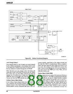
Packet is a frame that is addressed to the controller
and contains a data sequence anywhere in its data
field made up of 16 consecutive copies of the device’s
physical address (PADR[47:0]). The controller will
search incoming frames until it finds a Magic Packet
frame. It starts scanning for the sequence after pro-
cessing the length field of the frame. The data se-
quence can begin anywhere in the data field of the
frame, but must be detected before the controller
reaches the frame’s FCS field. Any deviation of the in-
coming frame’s data sequence from the required phys-
ical address sequence, even by a single bit, will
prevent the detection of that frame as a Magic Packet
frame.
When BCR45 is written to set the PMAT_MODE bit to
0, the Pattern Match logic is disabled and accesses to
the PMR are possible. Bits 6:0 of BCR45 specify the
address of the PMR word to be accessed. Writing to
BCR45 does not immediately affect the contents of the
PMR. Following the write to BCR45, the PMR word ad-
dressed by bits 6:0 of BCR45 may be read by reading
BCR45, BCR46, and BCR47 in any order. To write to
the PMR word, the write to BCR45 must be followed
by a write to BCR46 and a write to BCR47 in that order
to complete the operation. The PMR will not actually be
written until the write to BCR47 is complete.
The controller supports two different modes of address
detection for a Magic Packet frame. If MPPLBA (CSR5,
bit 5) or EMPPLBA (CSR116, bit 6) are at their default
value of 0, the controller will only detect a Magic Packet
frame if the destination address of the packet matches
the content of the physical address register (PADR). If
MPPLBA or EMPPLBA are set to 1, the destination ad-
dress of the Magic Packet frame can be unicast, multi-
cast, or broadcast.
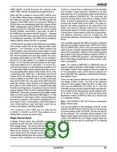
The first two 40-bit words in this RAM serve as pointers
and contain enable bits for the eight possible match
patterns. The remainder of the RAM contains the
match patterns and associated match pattern control
bits. Byte 0 of the first word contains the pattern enable
bits. Any bit position set in this byte enables the corre-
sponding match pattern in the PMR, as an example if
the bit 3 is set, then pattern 3 is enabled for matching.
Bytes 1 to 4 in the first word are pointers to the begin-
ning of the patterns 0 to 3, and bytes 1 to 4 in the sec-
ond word are pointers to the beginning of patterns 4 to
7, respectively. Byte 0 of the second word has no func-
tion associated with it. Byte 0 of the words 2 to 63 is the
control field of the PMR. Bit 7 of this field is the End of
Packet (EOP) bit. When this bit is set, it indicates the
end of a pattern in the PMR. Bits 6-4 of the control field
byte are the SKIP bits. The value of the SKIP field indi-
cates the number of the Dwords to be skipped before
the pattern in this PMR word is compared with data
from the incoming frame. A maximum of seven Dwords
may be skipped. Bits 3-0 of the control field byte are the
MASK bits. These bits correspond to the pattern match
bytes 3-0 of the same PMR word (PMR bytes 4-1). If bit
n of this field is 0, then byte n of the corresponding pat-
tern word is ignored. If this field is programmed to 3,
then bytes 0 and 1 of the pattern match field (bytes 2
and 1 of the word) are used, and bytes 3 and 2 are ig-
nored in the pattern matching operation.
Note: The setting of MPPLBA or EMPPLBA only ef-
fects the address detection of the Magic Packet frame.
The Magic Packet’s data sequence must be made up
of 16 consecutive copies of the device’s physical ad-
dress (PADR[47:0]), regardless of what kind of destina-
tion address it has.
There are two general methods to place the controller
into Magic Packet mode. The first is the software
method. In this method, either the BIOS or other soft-
ware sets the MPMODE bit (CSR5, bit 1). Then the
controller must be put into suspend mode (see descrip-
tion of CSR5, bit 0), allowing any current network activ-
ity to finish. Finally, either PG must be deasserted
(hardware control), or MPEN (CSR5, bit 2) must be set
to 1 (software control).
Note: FASTSPNDE (CSR7, bit 15) has no meaning in
Magic Packet mode.
The second method is the hardware method. In this
method, the MPPEN bit (CSR116, bit 4) is set at power
up by the loading of the EEPROM. This bit can also be
set by software. The controller will be placed in the
Magic Packet Mode when either the PG input is deas-
serted or the MPEN bit is set. Magic Packet mode can
be disabled at any time by asserting PG or clearing
MPEN bit.
The contents of the PMR are not affected by
H_RESET, S_RESET, or STOP. The contents are un-
defined after a power up reset (POR).
Magic Packet Mode
In Magic Packet mode, the controller remains fully
powered up (all VDD and VDDB pins must remain at
their supply levels). The device will not generate any
bus master transfers. No transmit operations will be ini-
tiated on the network. The device will continue to re-
ceive frames from the network, but all frames will be
automatically flushed from the receive FIFO. Slave ac-
cesses to the controller are still possible. A Magic
Am79C978
89

 AMD [ AMD ]