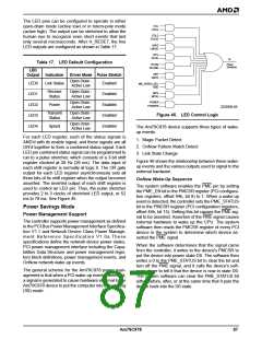
The LED pins can be configured to operate in either
open-drain mode (active low) or in totem-pole mode
(active high). The output can be stretched to allow the
human eye to recognize even short events that last
only several microseconds. After H_RESET, the five
LED outputs are configured as shown in Table 17.
COL
COLE
FDLS
FDLSE
LNKS
LNKSE
RCV
RCVE
To
Table 17. LED Default Configuration
LED
Pulse
Stretcher
RCVM
RCVME
XMT
XMTE
Output
Indication
Driver Mode Pulse Stretch
Open Drain -
Enabled
LED0
Link Status
MR_SPEED_SEL
100E
Active Low
Receive
Status
Open Drain -
Enabled
MPS
LED1
LED2
LED3
LED4
Active Low
MPSE
POWER
Open Drain -
Enabled
Power
POWERE
22206B-49
Active Low
Transmit
Status
Open Drain -
Enabled
Figure 45. LED Control Logic
Active Low
Open Drain -
Enabled
Speed
The Am79C978 device supports three types of wake-
up events:
Active Low
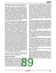
For each LED register, each of the status signals is
AND’d with its enable signal, and these signals are all
OR’d together to form a combined status signal. Each
LED pin combined status signal can be programmed to
run to a pulse stretcher, which consists of a 3-bit shift
register clocked at 38 Hz (26 ms). The data input of
each shift register is normally at logic 0. The OR gate
output for each LED register asynchronously sets all
three bits of its shift register when the output becomes
asserted. The inverted output of each shift register is
used to control an LED pin. Thus, the pulse stretcher
provides 2 to 3 clocks of stretched LED output, or 52
ms to 78 ms. See Figure 45.
1. Magic Packet Detect
2. OnNow Pattern Match Detect
3. Link State Change
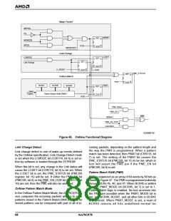
Figure 46 shows the relationship between these wake-
up events and the various outputs used to signal to the
external hardware.
OnNow Wake-Up Sequence
The system software enables the PME pin by setting
the PME_EN bit in the PMCSR register (PCI configura-
tion registers, offset 44h, bit 8) to 1. When a wake-up
event is detected, the controller sets the PME_STATUS
bit in the PMCSR register (PCI configuration registers,
offset 44h, bit 15). Setting this bit causes the PME sig-
nal to be asserted. Assertion of the PME signal causes
external hardware to wake up the CPU. The system
software then reads the PMCSR register of every PCI
device in the system to determine which device as-
serted the PME signal.
Power Savings Mode
Power Management Support
The controller supports power management as defined
in the PCI Bus Power Management Interface Specifica-
tion V1.1 and Network Device Class Power Manage-
ment Reference Specification V1.0a.These
specifications define the network device power states,
PCI power management interface including the Capa-
bilities Data Structure and power management regis-
ters block definitions, power management events, and
OnNow network wake-up events.
When the software determines that the signal came
from the controller, it writes to the device's PMCSR to
put the device into power state D0. The software then
writes a 0 to the PME_STATUS bit to clear the bit and
turn off the PME signal, and it calls the device's soft-
ware driver to tell it that the device is now in state D0.
The system software can clear the PME_STATUS bit
either before, after, or at the same time that it puts the
device back into the D0 state.
The general scheme for the Am79C978 power man-
agement is that when a PCI wake-up event is detected,
a signal is generated to cause hardware external to the
Am79C978 device to put the computer into the working
(S0) mode.
Am79C978
87

 AMD [ AMD ]