RST pin is deasserted. If the sampled value of EESK/
LED1 is a 0, the controller assumes that an external
pull-down device is holding the EESK/LED1 pin low, in-
dicating that there is no EEPROM in the system. Note
that if the designer creates a system that contains an
LED circuit on the EESK/LED1 pin, but has no EE-
PROM present, then the EEPROM auto-detection
function will incorrectly conclude that an EEPROM is
present in the system. However, this will not pose a
problem for the controller, since the checksum verifica-
tion will fail.
EEPROM Interface
The controller contains a built-in capability for reading
and writing to an external serial 93C46 EEPROM. This
built-in capability consists of an interface for direct con-
nection to a 93C46 compatible EEPROM, an automatic
EEPROM read feature, and a user-programmable reg-
ister that allows direct access to the interface pins.
Automatic EEPROM Read Operation
Shortly after the deassertion of the RST pin, the con-
troller will read the contents of the EEPROM that is at-
tached to the interface. Because of this automatic-read
capability of the controller, an EEPROM can be used to
program many of the features of the controller at
power-up, allowing system-dependent configuration in-
formation to be stored in the hardware instead of inside
the device driver.
Direct Access to the Interface
The user may directly access the port through the
EEPROM register, BCR19. This register contains bits
that can be used to control the interface pins. By per-
forming an appropriate sequence of accesses to
BCR19, the user can effectively write to and read from
the EEPROM. This feature may be used by a system
configuration utility to program hardware configuration
information into the EEPROM.
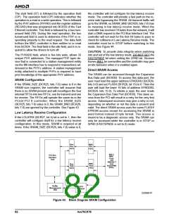
If an EEPROM exists on the interface, the controller will
read the EEPROM contents at the end of the
H_RESET operation. The EEPROM contents will be
serially shifted into a temporary register and then sent
to various register locations on board the controller. Ac-
cess to the Am79C978 configuration space or any I/O
resource is not possible during the EEPROM read op-
eration. The controller will terminate any access at-
tempt with the assertion of DEVSEL and STOP while
TRDY is not asserted, signaling to the initiator to dis-
connect and retry the access at a later time.
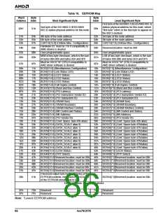
EEPROM-Programmable Registers
The following registers contain configuration informa-
tion that will be programmed automatically during the
EEPROM read operation:
n I/O offsets 0h-Fh Address PROM locations
n BCR2
n BCR4
n BCR5
n BCR6
n BCR7
n BCR9
n BCR18
n BCR22
n BCR23
n BCR24
n BCR25
n BCR26
n BCR27
n BCR32
n BCR33
n BCR35
n BCR36
Miscellaneous Configuration
LED0 Status
A checksum verification is performed on the data that
is read from the EEPROM. If the checksum verification
passes, PVALID (BCR19, bit 15) will be set to 1. If the
checksum verification of the EEPROM data fails,
PVALID will be cleared to 0, and the controller will force
all EEPROM-programmable BCR registers back to
their H_RESET default values. However, the content of
the Address PROM locations (offsets 0h - Fh from the
I/O or memory mapped I/O base address) will not be
cleared. The 8-bit checksum for the entire 82 bytes of
the EEPROM should be FFh.
LED1 Status
LED2 Status
LED3 Status
Full-Duplex Control
Burst and Bus Control
PCI Latency
PCI Subsystem Vendor ID
PCI Subsystem ID
SRAM Size
If no EEPROM is present at the time of the automatic
read operation, the controller will recognize this condi-
tion, abort the automatic read operation, and clear both
the PREAD and PVALID bits in BCR19. All EEPROM-
programmable BCR registers will be assigned their de-
fault values after H_RESET. The content of the Ad-
dress PROM locations (offsets 0h - Fh from the I/O or
memory mapped I/O base address) will be undefined.
SRAM Boundary
SRAM Interface Control
PHY Control and Status
PHY Address
PCI Vendor ID
PCI Power Management Capa-
bilities (PMC) Alias Register
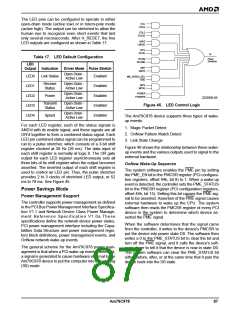
EEPROM Auto-Detection
The controller uses the EESK/LED1 pin to determine if
an EEPROM is present in the system. At the rising
edge of CLK during the last clock during which RST is
asserted, the controller will sample the value of the
EESK/LED1 pin. If the sampled value is a 1, then the
controller assumes that an EEPROM is present, and
the EEPROM read operation begins shortly after the
n BCR37
n BCR38
n BCR39
PCI DATA Register 0 (DATA0)
Alias Register
PCI DATA Register 1 (DATA1)
Alias Register
PCI DATA Register 2 (DATA2)
Alias Register
84
Am79C978

 AMD [ AMD ]