D A T A S H E E T
COMMAND DEFINITIONS
Writing specific address and data commands or se-
quences into the command register initiates device
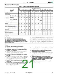
operations. The Command Definitions table defines the
valid register command sequences. Writing incorrect
address and data values or writing them in the im-
proper sequence resets the device to reading array
data.
however, the device ignores reset commands until the
operation is complete.
The reset command may be written between the se-
quence cycles in an autoselect command sequence.
Once in the autoselect mode, the reset command must
be written to return to reading array data (also applies
to autoselect during Erase Suspend).
All addresses are latched on the falling edge of WE# or
CE#, whichever happens later. All data is latched on
the rising edge of WE# or CE#, whichever happens
first. Refer to the appropriate timing diagrams in the
“AC Characteristics” section.
If DQ5 goes high during a program or erase operation,
writing the reset command returns the device to read-
ing array data (also applies during Erase Suspend).
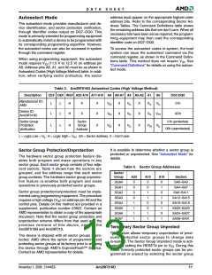
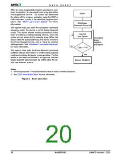
Autoselect Command Sequence
The autoselect command sequence allows the host
system to access the manufacturer and devices codes,
and determine whether or not a sector is protected.
The Command Definitions table shows the address
and data requirements. This method is an alternative to
that shown in the Autoselect Codes (High Voltage
Method) table, which is intended for PROM program-
Reading Array Data
The device is automatically set to reading array data
after device power-up. No commands are required to
retrieve data. The device is also ready to read array
data after completing an Embedded Program or Em-
bedded Erase algorithm.
After the device accepts an Erase Suspend command,
the device enters the Erase Suspend mode. The sys-
tem can read array data using the standard read
timings, except that if it reads at an address within
erase-suspended sectors, the device outputs status
data. After completing a programming operation in the
Erase Suspend mode, the system may once again
read array data with the same exception. See “Erase
Suspend/Erase Resume Commands” for more infor-
mation on this mode.
mers and requires V on address bit A9.
ID
The autoselect command sequence is initiated by
writing two unlock cycles, followed by the autoselect
command. The device then enters the autoselect
mode, and the system may read at any address any
number of times, without initiating another command
sequence.
A read cycle at address XX00h retrieves the manufac-
turer code. A read cycle at address XX01h returns the
device code. A read cycle containing a sector address
(SA) and the address 02h in returns 01h if that sector
is protected, or 00h if it is unprotected. Refer to the
Sector Address tables for valid sector addresses.
The system must issue the reset command to re-en-
able the device for reading array data if DQ5 goes high,
or while in the autoselect mode. See the “Reset Com-
mand” section, next.
The system must write the reset command to exit the
autoselect mode and return to reading array data.
See also “Requirements for Reading Array Data” in the
“Device Bus Operations” section for more information.
The Read Operations table provides the read parame-
ters, and Read Operation Timings diagram shows the
timing diagram.
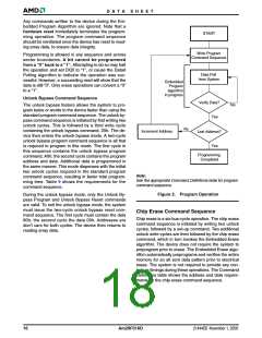
Byte Program Command Sequence
Programming is a four-bus-cycle operation. The pro-
gram command sequence is initiated by writing two
unlock write cycles, followed by the program set-up
command. The program address and data are written
next, which in turn initiate the Embedded Program al-
gorithm. The system is not required to provide further
controls or timings. The device automatically provides
internally generated program pulses and verify the pro-
grammed cell margin. The Command Definitions take
shows the address and data requirements for the byte
program command sequence.
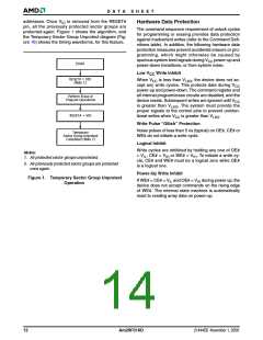
Reset Command
Writing the reset command to the device resets the de-
vice to reading array data. Address bits are don’t care
for this command.
The reset command may be written between the se-
quence cycles in an erase command sequence before
erasing begins. This resets the device to reading array
data. Once erasure begins, however, the device ig-
nores reset commands until the operation is complete.
When the Embedded Program algorithm is complete,
the device then returns to reading array data and ad-
dresses are no longer latched. The system can
determine the status of the program operation by using
DQ7, DQ6, or RY/BY#. See “Write Operation Status”
for information on these status bits.
The reset command may be written between the se-
quence cycles in a program command sequence
before programming begins. This resets the device to
reading array data (also applies to programming in
Erase Suspend mode). Once programming begins,
November 1, 2006 21444E6
Am29F016D
15

 AMD [ AMD ]