D A T A S H E E T
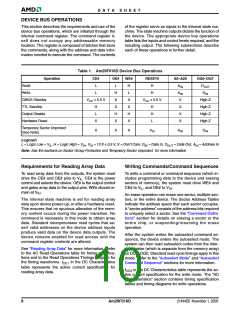
address must appear on the appropriate highest order
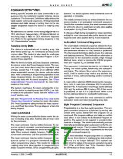
Autoselect Mode
address bits. Refer to the corresponding Sector Ad-
dress Tables. The Command Definitions table shows
the remaining address bits that are don’t care. When all
necessary bits have been set as required, the program-
ming equipment may then read the corresponding
identifier code on DQ7–DQ0.
The autoselect mode provides manufacturer and de-
vice identification, and sector protection verification,
through identifier codes output on DQ7–DQ0. This
mode is primarily intended for programming equipment
to automatically match a device to be programmed with
its corresponding programming algorithm. However,
the autoselect codes can also be accessed in-system
through the command register.
To access the autoselect codes in-system, the host
system can issue the autoselect command via the
command register, as shown in the Command Defini-
When using programming equipment, the autoselect
mode requires V (11.5 V to 12.5 V) on address pin
tions table. This method does not require V . See
ID
ID
“Command Definitions” for details on using the autose-
lect mode.
A9. Address pins A6, A1, and A0 must be as shown in
Autoselect Codes (High Voltage Method) table. In addi-
tion, when verifying sector protection, the sector
Table 3. Am29F016D Autoselect Codes (High Voltage Method)
CE# OE# WE# A20-A18 A17-A10 A9 A8-A7 A6 A5-A2 A1 A0
Description
DQ7-DQ0
Manufacturer ID:
AMD
L
L
L
L
H
H
X
X
X
X
VID
VID
X
X
VIL
VIL
X
X
VIL VIL
01h
Device ID:
Am29F016D
VIL VIH
ADh
Sector Group
Protection
Verification
Sector
Group
Address
01h (protected)
L
L
H
X
VID
X
VIL
X
VIH VIL
00h (unprotected)
L = Logic Low = VIL, H = Logic High = VIH, SA = Sector Address, X = Don’t care.
It is possible to determine whether a sector group is
protected or unprotected. See “Autoselect Mode” for
details.
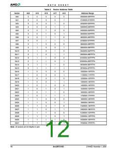
Sector Group Protection/Unprotection
The hardware sector group protection feature dis-
ables both program and erase operations in any
sector group. Each sector group consists of four adja-
cent sectors. Table 4 shows how the sectors are
grouped, and the address range that each sector
group contains. The hardware sector group unprotec-
tion feature re-enables both program and erase
operations in previously protected sector groups.
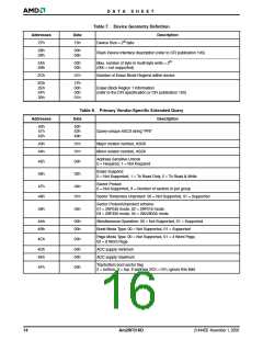
Table 4. Sector Group Addresses
Sector
Group
SGA0
SGA1
SGA2
SGA3
SGA4
SGA5
SGA6
SGA7
A20
A19
A18
Sectors
0
0
0
SA0–SA3
0
0
1
SA4–SA7
Sector group protection/unprotection must be imple-
mented using programming equipment. The procedure
0
1
0
SA8–SA11
SA12–SA15
SA16–SA19
SA20–SA23
SA24–SA27
SA28–SA31
0
1
1
requires a high voltage (V ) on address pin A9 and the
ID
1
0
0
control pins. Details on this method are provided in a
supplement, publication number 23922. Contact an
AMD representative to obtain a copy of the appropriate
document. Note that the sector group protection and
unprotection scheme differs from that used with the
previous versions of this device, namely the
Am29F016B and Am29F016.
1
0
1
1
1
0
1
1
1
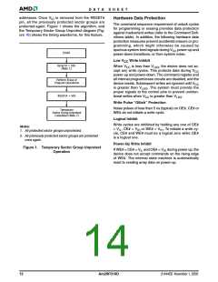
Temporary Sector Group Unprotect
This feature allows temporary unprotection of previ-
ously protected sector groups to change data
in-system. The Sector Group Unprotect mode is acti-
The device is shipped with all sector groups unpro-
tected. AMD offers the option of programming and
protecting sector groups at its factory prior to shipping
the device through AMD’s ExpressFlash™ Service.
Contact an AMD representative for details.
vated by setting the RESET# pin to V . During this
ID
mode, formerly protected sector groups can be pro-
grammed or erased by selecting the sector group
November 1, 2006 21444E6
Am29F016D
11

 AMD [ AMD ]