Revision 1.02 – April 12, 2007
S5920 – PCI Product: Pass-Thru Operation
Data Book
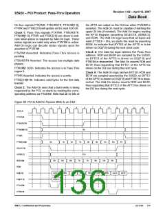
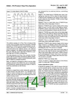
Figure 73. Active Mode PCI Write without PTADR#
is not considered active until PTATN# is low and
PTWAIT# is high) regardless of the transfer being a
read or a write. Figure 13b shows a PCI read cycle
with PTADR# disabled.
1
2
3
4
5
6
7
ADCLK
PTATN#
PTBURST#
PTNUM[1:0]
PTWR
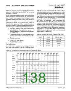
Figure 13c shows a Pass-Thru write cycle with
PTADR# disabled.
Active mode Programmable Wait States
01b
Bits 0,1,2 of the PTCR register control this feature.
Wait States are programmed on a per region basis.
For example: region one can be set for zero wait
states while other regions may have multiple wait
states programmed.
PTBE[3:0]
DXFR#
0h
Fh
DQ[31:0]
PTWAIT#
PTADR#
DATA
Wait state options are 0,1,2,...7 wait states. The S5920
will always count N wait states (N=0,1,..7) before com-
pleting the current data phase.
Figures 17, 18 and 19 show Pass-Thru transfers with
programmed wait states.
PTRDY#/PTWAIT#
When PTADR# is active (low), the S5920 will drive the
DQ[31:0] bus with the 32-bit PCI address regardless of
the PTMODE pin. To avoid contention on the DQ[31:0]
bus during PCI read cycles, the S5920 incorporates a
turnaround cycle before starting to drive the data
(DXFR# assertion). This is needed only when
PTADR# is enabled and when zero wait states are
programmed during a Pass-Thru read cycle. The cycle
immediately following the address cycle will be a turn-
around cycle as shown in Figure 13a.
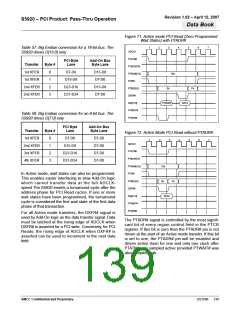
In Active mode, the PTRDY#/PTWAIT# pin takes the
PTWAIT# function, which is the opposite function of
this pin when configured for passive mode. That is, if
the part is configured to operate in Active mode,
PTWAIT# asserted low means the Add-On wishes to
insert wait states.
Add-On peripherals are allowed to insert wait state
cycles at any time during an Active mode transfer.
When PTWAIT# has been sampled low, the S5920 will
tri-state its DQ[31:0] bus in order to allow other Add-
On devices to use the bus without contention.
If PTADR# is disabled, the DXFR# output will be
driven one clock cycle after PTATN# is valid (PTATN#
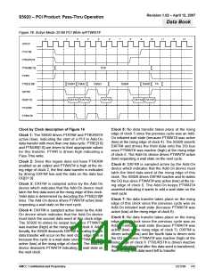
Figure 74. Active Mode PCI Write with Add-On Initiated Wait States Using PTWAIT#
3
4
7
8
9
0
1
2
5
6
10
11
12
13
ADCLK
PTATN#
PTBURST#
PTNUM[1:0]
PTWR
01b
0h
PTBE[3:0]#
DXFR#
Fh
DQ[31:0]
PTADR#
PTWAIT#
PTADDR
DATA
AMCC Confidential and Proprietary
DS1596
140

 AMCC [ APPLIED MICRO CIRCUITS CORPORATION ]