Revision 1.02 – April 12, 2007
S5920 – PCI Product: Pass-Thru Operation
Data Book
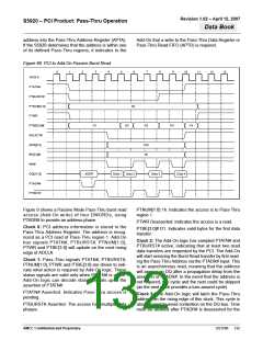
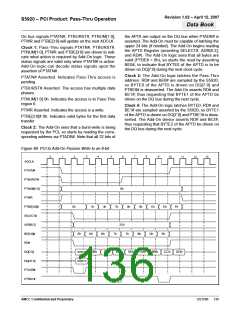
On bus signals PTATN#, PTBURST#, PTNUM[1:0],
PTWR and PTBE[3:0] will update on the next ADCLK.
the APTA are output on the DQ bus when PTADR# is
asserted. The Add-On must be capable of latching the
upper 24 bits (if needed). The Add-On begins reading
the APTD Register (asserting SELECT#, ADR[6:2],
and RD#). The Add-On logic sees that all bytes are
valid (PTBE# = 0h), so starts the read by asserting
BE0#, to indicate that BYTE0 of the APTD is to be
driven on DQ[7:0] during the next clock cycle.
Clock 1: Pass-Thru signals PTATN#, PTBURST#,
PTNUM[1:0], PTWR and PTBE[3:0] are driven to indi-
cate what action is required by Add-On logic. These
status signals are valid only when PTATN# is active.
Add-On logic can decode status signals upon the
assertion of PTATN#.
Clock 3: The Add-On logic latches the Pass-Thru
address. RD# and BE0# are sampled by the S5920,
so BYTE0 of the APTD is driven on DQ[7:0] and
PTBE0# is deasserted. The Add-On asserts RD# and
BE1#, thus requesting that BYTE1 of the APTD be
driven on the DQ bus during the next cycle.
PTATN# Asserted. Indicates Pass-Thru access is
pending.
PTBURST# Asserted. The access has multiple data
phases.
PTNUM[1:0] 0h. Indicates the access is to Pass-Thru
region 0.
Clock 4: The Add-On logic latches BYTE0. RD# and
BE1# are sampled asserted by the S5920, so BYTE1
of the APTD is driven on DQ[7:0] and PTBE1# is deas-
serted. The Add-On device asserts RD# and BE2#,
thus requesting that BYTE2 of the APTD be driven on
the DQ bus during the next cycle.
PTWR Asserted. Indicates the access is a write.
PTBE[3:0]# 0h. Indicates valid bytes for the first data
transfer.
Clock 2: The Add-On sees that a burst-write is being
requested by the PCI, so starts by reading the corre-
sponding address via PTADR#. Note that all 32 bits of
Figure 69. PCI to Add-On Passive Write to an 8-bit
3
4
7
8
9
0
1
2
5
6
10
11
12
13
ADCLK
PTATN#
PTBURST#
PTNUM[1:0]
PTWR
0h
PTBE[3:0]#
SELECT#
ADR[6:2]
BE[3:0]#
RD#
0h
1h
3h
7h
0h
8h
Ch
Eh
Fh
2Ch
Eh
Dh
Bh
7h
7h
Bh
Dh
Eh
ADD[7:0]
DQ[7:0]
30h
9Ah
D4h
08h
AAh
BBh
CCh
DDh
ADD[31:8]
DQ[31:8]
PTADR#
PTRDY#
AMCC Confidential and Proprietary
DS1596
136

 AMCC [ APPLIED MICRO CIRCUITS CORPORATION ]