Revision 1.02 – April 12, 2007
S5920 – PCI Product: Pass-Thru Operation
Data Book
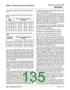
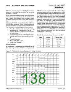
When the device is programmed for Big Endian trans-
lation and a 32-bit data bus, the S5920 will convert as
described in Table 3.
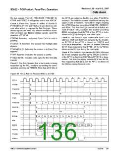
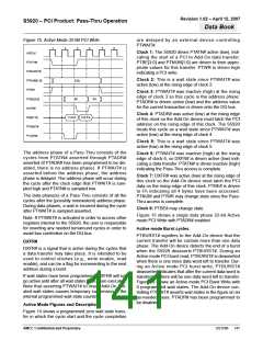
PTADR# has been programmed to be output it will go
active (low) at this time, and the data presented on the
DQ bus is the address for the current transaction. Add-
On logic may latch the address value at the rising
edge of the clock. Address cycles do not count toward
the number of wait states needed to complete data
phases. In Active mode, the PTRDY# pin is renamed
to PTWAIT#. On cycles after PTWAIT# is sampled low,
the state machine is idle. Idle cycles are also not
counted as wait states by the S5920. To control the
number of wait states on an as-needed basis only,
zero wait states should be programmed and PTWAIT#
can be driven low when wait states are to be inserted.
If PTWAIT# is low when PTATN# is asserted by the
S5920, the pending transfer cycle won’t be started
until PTWAIT# is driven high.
Active mode is provided to simplify logic requirements
when interfacing an application to the Add-On Local
bus. Passive mode requires Add-On logic to assert
read/write signals and drive or latch data on the DQ
bus.
Strapping PTMODE low configures the S5920 for
Active mode operation. Active mode allows more
designer flexibility through programmable features.
The following is a brief description of these features.
•
Pass-Thru address can be driven automatically
at the beginning of all transfers or can be
skipped altogether if addresses are unneeded
by Add-On logic.
•
Programmed or Add-On controlled wait states
to delay data transfers automatically or on the
fly.
Table 56. Showing Big Endian Conversion for 32-bit
Byte#
PCI Byte
D7-D0
Add-On Byte
D31-D24
D23-D16
D15-D8
•
•
•
Endian Conversion
0
1
2
3
Write FIFO ( Write posting )
Read FIFO ( Prefetch )
D15-D8
D23-D15
D31-D24
Active Operation
D7-D0
In Active mode, a data transfer start is signaled on the
first clock edge in which PTATN# is sampled low. If
Figure 70. PCI to Add-On Passive Read to an 16-bit Add-On Device
3
4
7
8
9
0
1
2
5
6
10
11
12
13
ADCLK
PTATN#
PTBURST#
PTNUM[1:0]
PTWR
3h
PTBE[3:0]#
SELECT#
ADR[6:2]
BE[3:0]#
WR#
0h
3h
0h
3h
0h
3h
Fh
2Ch
Ch
3h
Ch
3h
Ch
3h
ADDR
[31:16]
DQ[31:16]
DQ[15:0]
PTADR#
PTRDY#
ADDR
[15:0]
D1
D1
D2
D2
D3
D3
LOW
HIGH
LOW
HIGH
LOW
HIGH
AMCC Confidential and Proprietary
DS1596
138

 AMCC [ APPLIED MICRO CIRCUITS CORPORATION ]