S2042/S2048
HIGH PERFORMANCE SERIAL INTERFACE CIRCUITS
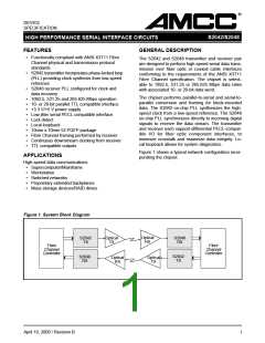
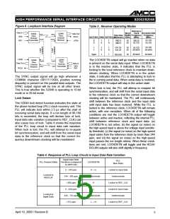
Figure 6. Loopback Interface Diagram
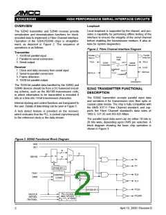
Table 3 . Receiver Operating Modes
Reference
Clock RCLK/RCLKN
Width Frequency Frequency
Data In
Word
S2048
Fibre
Channel
Receiver
S2042
Fibre
Channel
Transmitter
Data Out
RCLK
TX/Y
RX/Y
Data Rate
(Mbits/sec)
OE0
OE1
RATESEL DWS REFSEL
(Bits)
(MHz)
(MHz)
TLX/Y
RLX/Y
0
0
1
0
1
0
10
20
106.25
53.125
53.125
53.125
LPEN
1062.5
1062.5
1
1
1
0
1
0
10
20
53.125
26.5625
53.125
26.5625
531.25
531.25
Open
1
1
10
26.5625
26.5625
265.625
LPEN
S2042
Fibre
Channel
S2048
Fibre
Channel
Receiver
The LOCKDETN output will go inactive when no data
is present on the serial data input. When LOCKDETN
is in the inactive state, it indicates that the PLL is
locking to the local reference clock to maintain down-
stream clocking. When LOCKDETN is in the active
state, it indicates that the PLL is attempting to lock to
the in coming serial data. When serial data is restored,
the LOCKDETN output will stay in the active state.
RLX/Y
RX/Y
TLX/Y
Data Out
Data In
OE0
OE1
TX/Y Transmitter
RCLK
The SYNC output signal will go high whenever a
COMMA character (0011111XXX, positive running
disparity) is present on the parallel data outputs. The
SYNC output signal will be low at all other times.
This is true whether the S2048 is operating in 10-bit
mode or in 20-bit mode.
When lock is lost, the PLL will attemp to reaquire bit
synchronization, and will shift from the serial input data
to the reference clock so that the correct downstream
clocking will be maintained. The PLL will continuously
shift between the reference clock and the input data
until input data has been restored. While the PLL is
locked to the reference clock, LOCKDETN will remain
active, with one exception. When all of the following
conditions are met the LOCKDETN output will toggle
between active and inactive, reflecting the internal PLL
shift between reference clock and input data: (a)
LOCKREFN is not active, (b) the signal (or noise) on
the high-speed input is above the voltage input sensitiv-
ity threshold, (c) the signal (or noise) on the high-speed
input varies from the reference clock by more than 244
ppm, and (d) the signal (or noise) on the high-speed
input passes the run length criteria. When these condi-
tions are met, LOCKDETN will toggle and the RCLK/
RCLKN outputs will also shift slightly in frequency.
Lock Detect
The S2048 lock detect function indicates the state of
the phase-locked loop (PLL) clock recovery unit. The
PLL will indicate lock within 2.5 µs after the start of
receiving serial data inputs. If a run length of 80-160
bits is exceeded, the loop will declare loss of lock.
Input data rate variation (compared to REF_CLK) can
also cause loss of lock. Table 4 shows the response
of the PLL loop circuit to input data rate variation.
When lock is lost, the PLL will attempt to re-aquire
bit synchronization, and will shift from the serial input
data to the reference clock so that the correct fre-
quency downstream clocking will be maintained.
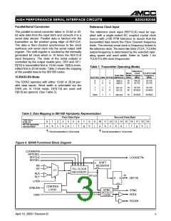
Table 4. Response of PLL Loop Circuit to Input Data Rate Variation
Input Data Rate
Variation (compared
to REFCLK)
PLL
LOCKDETN
PLL Present State
New State
0 - 244 ppm
244 - 366 ppm
>366 ppm
H -->L
Locked to input data
Indeterminate
Locked to
REFCLK
Indeterminate
H
L
Locked to REF_CLK
Locked to Input Data
Indeterminate
0 - 448 ppm
448 - 752 ppm
>752 ppm
Locked to
Input Data
Indeterminate
L -->H
Locked to REF_CLK
April 10, 2000 / Revision B
5

 AMCC [ APPLIED MICRO CIRCUITS CORPORATION ]