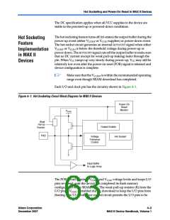
Hot Socketing and Power-On Reset in MAX II Devices
Entry into user mode is gated by whether all VCCIO banks are powered
with sufficient operating voltage. If VCCINT and VCCIO are powered
simultaneously, the device enters user mode within the tCONFIG
specifications. If VCCIO is powered more than tCONFIG after VCCINT, the
device does not enter user mode until 2 µs after all VCCIO banks are
powered.
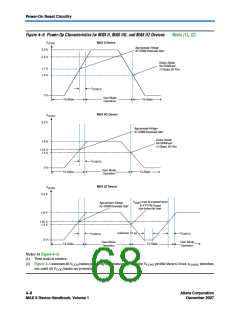
For MAX II and MAX IIG devices, when in user mode, the POR circuitry
continues to monitor the VCCINT (but not VCCIO) voltage level to detect a
brown-out condition. If there is a VCCINT voltage sag at or below 1.4 V
during user mode, the POR circuit resets the SRAM and tri-states the I/O
pins. Once VCCINT rises back to approximately 1.7 V (or 1.55 V for
MAX IIG devices), the SRAM download restarts and the device begins to
operate after tCONFIG time has passed.
For MAX IIZ devices, the POR circuitry does not monitor the VCCINT and
VCCIO voltage levels after the device enters user mode. If there is a VCCINT
voltage sag below 1.4 V during user mode, the functionality of the device
will not be guaranteed and you must power down the VCCINT to 0 V for a
minimum of 10 µs before powering the VCCINT and VCCIO up again. Once
VCCINT rises from 0 V back to approximately 1.55 V, the SRAM download
restarts and the device begins to operate after tCONFIG time has passed.
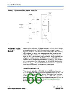
Figure 4–5 shows the voltages for POR of MAX II, MAX IIG, and
MAX IIZ devices during power-up into user mode and from user mode
to power-down or brown-out.
Altera Corporation
December 2007
4–7
MAX II Device Handbook, Volume 1

 ALTERA [ ALTERA CORPORATION ]