PLLs and Clock Networks
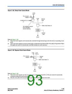
Figure 2–60. External PLL Output Clock Control Blocks
PLL Counter
Outputs (c[5..0])
6
Static Clock Select
(1)
Enable/
Disable
Internal
Logic
IOE (2)
Internal
Logic
Static Clock
Select
(1)
PLL_OUT
Pin
Notes to Figure 2–60:
(1) These clock select signals can only be set through a configuration file (SOF or POF) and cannot be dynamically
controlled during user mode operation.
(2) The clock control block feeds to a multiplexer within the PLL_OUTpin’s IOE. The PLL_OUTpin is a dual-purpose
pin. Therefore, this multiplexer selects either an internal signal or the output of the clock control block.
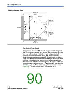
For the global clock control block, clock source selection can be controlled
either statically or dynamically. You has the option of statically selecting
the clock source by using the Quartus II software to set specific
configuration bits in the configuration file (SOF or POF) or you can control
the selection dynamically by using internal logic to drive the multiplexer
select inputs. When selecting statically, the clock source can be set to any
of the inputs to the select multiplexer. When selecting the clock source
dynamically, you can either select between two PLL outputs (such as the
C0or C1outputs from one PLL), between two PLLs (such as the C0/C1
clock output of one PLL or the C0/C1c1ock output of the other PLL),
between two clock pins (such as CLK0or CLK1), or between a
combination of clock pins or PLL outputs.
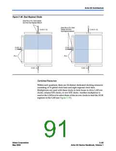
For the regional and PLL_OUTclock control block, clock source selection
can only be controlled statically using configuration bits. Any of the
inputs to the clock select multiplexer can be set as the clock source.
2–86
Altera Corporation
May 2008
Arria GX Device Handbook, Volume 1

 ALTERA [ ALTERA CORPORATION ]