High-Speed Differential I/O with DPA Support
For high-speed source synchronous interfaces such as POS-PHY 4 and the
Parallel RapidIO standard, the source synchronous clock rate is not a
byte- or SERDES-rate multiple of the data rate. Byte alignment is
necessary for these protocols since the source synchronous clock does not
provide a byte or word boundary since the clock is one half the data rate,
not one eighth. The Arria GX device’s high-speed differential I/O
circuitry provides dedicated data realignment circuitry for
user-controlled byte boundary shifting. This simplifies designs while
saving ALM resources. You can use an ALM-based state machine to
signal the shift of receiver byte boundaries until a specified pattern is
detected to indicate byte alignment.
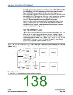
Fast PLL and Channel Layout
The receiver and transmitter channels are interleaved such that each I/O
bank on the left side of the device has one receiver channel and one
transmitter channel per LAB row. Figure 2–81 shows the fast PLL and
channel layout in the EP1AGX20C, EP1AGX35C/D, EP1AGX50C/D and
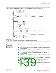
EP1AGX60C/D devices. Figure 2–82 shows the fast PLL and channel
layout in EP1AGX60E and EP1AGX90E devices.
Figure 2–81. Fast PLL and Channel Layout in the EP1AGX20C, EP1AGX35C/D, EP1AGX50C/D, EP1AGX60C/D
Devices Note (1)
4
LVDS
Clock
DPA
Clock
Quadrant
Quadrant
4
2
2
Fast
PLL 1
Fast
PLL 2
Quadrant
Quadrant
LVDS
Clock
DPA
Clock
4
Note to Figure 2–81:
(1) See Table 2–30 for the number of channels each device supports.
2–130
Altera Corporation
May 2008
Arria GX Device Handbook, Volume 1

 ALTERA [ ALTERA CORPORATION ]