Arria GX Architecture
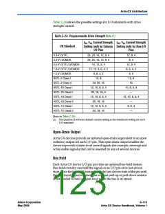
Table 2–24 shows the possible settings for I/O standards with drive
strength control.
Table 2–24. Programmable Drive Strength Note (1)
IOH / IOL Current Strength IOH / IOL Current Strength
I/O Standard
Setting (mA) for Column Setting (mA) for Row I/O
I/O Pins
Pins
3.3-V LVTTL
24, 20, 16, 12, 8, 4
24, 20, 16, 12, 8, 4
16, 12, 8, 4
12, 8, 4
8, 4
3.3-V LVCMOS
2.5-V LVTTL/LVCMOS
1.8-V LVTTL/LVCMOS
1.5-V LVCMOS
12, 8, 4
8, 6, 4, 2
4, 2
12, 10, 8, 6, 4, 2
8, 6, 4, 2
SSTL-2 Class I
12, 8
12, 8
SSTL-2 Class II
SSTL-18 Class I
SSTL-18 Class II
HSTL-18 Class I
HSTL-18 Class II
HSTL-15 Class I
HSTL-15 Class II
24, 20, 16
16
12, 10, 8, 6, 4
20, 18, 16, 8
12, 10, 8, 6, 4
20, 18, 16
10, 8, 6, 4
—
12, 10, 8, 6, 4
—
12, 10, 8, 6, 4
20, 18, 16
8, 6, 4
—
Note to Table 2–24:
(1) The Quartus II software default current setting is the maximum setting for each
I/O standard.
Open-Drain Output
Arria GX devices provide an optional open-drain (equivalent to an open
collector) output for each I/O pin. This open-drain output enables the
device to provide system-level control signals (for example, interrupt and
write enable signals) that can be asserted by any of several devices.
Bus Hold
Each Arria GX device I/O pin provides an optional bus-hold feature.
Bus-hold circuitry can hold the signal on an I/O pin at its last-driven
state. Since the bus-hold feature holds the last-driven state of the pin until
the next input signal is present, an external pull-up or pull-down resistor
is not needed to hold a signal level when the bus is tri-stated.
Altera Corporation
May 2008
2–115
Arria GX Device Handbook, Volume 1

 ALTERA [ ALTERA CORPORATION ]