I/O Structure
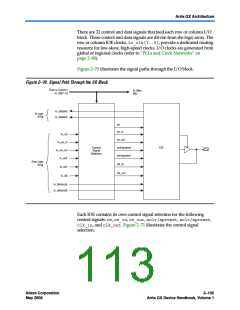
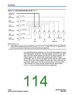
Figure 2–71. Control Signal Selection per IOE Note (1)
Dedicated I/O
Clock [7..0]
io_oe
Local
Interconnect
io_sclr
Local
Interconnect
io_aclr
Local
Interconnect
io_ce_out
Local
Interconnect
io_ce_in
io_clk
Local
Interconnect
ce_out
clk_out
sclr/spreset
Local
Interconnect
clk_in
ce_in
aclr/apreset
oe
Notes to Figure 2–71:
(1) Control signals ce_in, ce_out, aclr/apreset, sclr/spreset, and oecan be global signals even though their
control selection multiplexers are not directly fed by the ioe_clk[7..0]signals. The ioe_clksignals can drive
the I/O local interconnect, which then drives the control selection multiplexers.
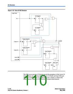
In normal bidirectional operation, you can use the input register for input
data requiring fast setup times. The input register can have its own clock
input and clock enable separate from the OE and output registers. The
output register can be used for data requiring fast clock-to-output
performance. You can use the OE register for fast clock-to-output enable
timing. The OE and output register share the same clock source and the
same clock enable source from the local interconnect in the associated
LAB, dedicated I/O clocks, and the column and row interconnects.
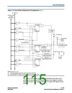
Figure 2–72 shows the IOE in bidirectional configuration.
2–106
Altera Corporation
May 2008
Arria GX Device Handbook, Volume 1

 ALTERA [ ALTERA CORPORATION ]