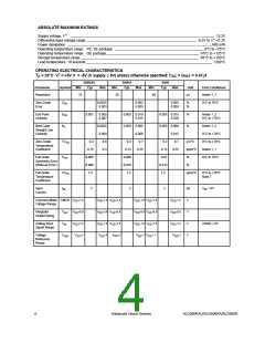
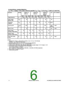
DC ELECTRICAL CHARACTERISTICS
T
= 25°C V supply = +5.0V unless otherwise specified; C = C
= 0.47µf, R
= 100KΩ(1% metal film)
A
AZ REF
REF
Parameter
Symbol
500RAU-10
500RA-10
500RAU-20
500RA-20
500RAU-50
Unit
Test Conditions
500RA-50
500R-50
Typ
Min
Typ
Max
Min
Typ
Max
Min
Max
Voltage Reference
V
R
0.998 1.000 1.002 0.997 1.000
1.003 0.995
1.000
1.005
V
Supply Voltage
Rejection Ratio
V
95
3
95
7
95
dB
RSR
Temperature
Coefficient
V
10
20
15
-0.08
10
50 ppm/C°
RTC
Long Term Drift
Warm Up Time
∆V
∆t
/
-0.08
10
-0.08
10
ppm/
1000hrs
Note 7
Note 7
REF
min.
Positive Supply
Operating Voltage Range
V+
V-
I
4.5
5.5
4.5
5.5
4.5
5.5
V
V
Negative Supply
Operating Voltage Range
-5.5
-4.5
-5.5
-4.5
-5.5
-4.5
Power Down Supply
Current
25
25
25
µA
Note 7
PD
NOTES:
1. Integrate time ≥ 66 msec., Auto Zero time ≥ 66 msec., V
= 4V, V = 2.0V Full Scale
IN
INT
Resolution = V
INT
/integrate time/clock period
2. End point linearity at ±1/4, ±1/2, ±3/4 Full Scale after Full Scale adjustment.
3. Rollover Error also depends on C , C , C characteristics.
INT REF AZ
~
4. Contact factory for other power supply operating voltage ranges, including Vsupply = ±3V or Vsupply = ±2.5V.
5. Recommended selection of clock periods of one of the following:
t clk = 0.27µsec, 0.54µsec, or 1.09µsec
which corresponds to clock frequencies of 3.6864 MHz, 1.8432 MHz, 0.9216 MHz respectively.
6.
R
REF
is 100K Ω 1% metal film, 50 ppm/C.
7. Sample tested parameter.
6
Advanced Linear Devices
ALD500RAU/ALD500RA/ALD500R

 ALD [ ADVANCED LINEAR DEVICES ]