[AK4679]
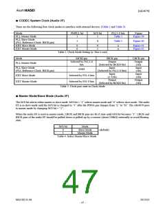
■ PLL Unlock State (Audio I/F)
1) PLL Master Mode (PMPLL bit = “1”, M/S bit = “1”)
In this mode, LRCK and BICK pins output “L” before the PLL goes to lock state after PMPLL bit = “0” Æ “1” (Table 8).
After the PLL is locked, a first period of LRCK and BICK may be invalid clock, but these clocks return to normal state
after a period of 1/fs.
When sampling frequency is changed, BICK and LRCK pins do not output irregular frequency clocks but go to “L” by
setting PMPLL bit “0”.
PLL State
BICK pin
LRCK pin
After that PMPLL bit “0” Æ “1”
PLL Unlock (except above case)
PLL Lock
“L” Output
Invalid
Table 9
“L” Output
Invalid
1fs Output
Table 8. Clock Operation in PLL Master Mode (PMPLL bit = “1”, M/S bit = “1”)
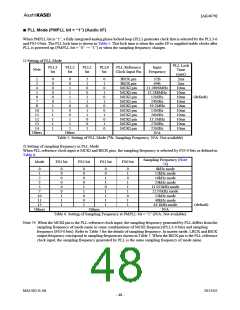
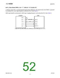
■ PLL Master Mode (PMPLL bit = “1”, M/S bit = “1”) (Audio I/F)
When an external clock (11.2896MHz, 12MHz, 12.288MHz, 13MHz, 13.5MHz, 19.2MHz, 24MHz, 25MHz, 26MHz or
27MHz) is input to the MCKI pin, the BICK and LRCK clocks are generated by an internal PLL circuit. MCKI input
frequency is selected by PLL3-0 bits (Table 5). The BICK output frequency is selected between 32fs or 64fs, by BCKO
bit (Table 9). Sampling frequency mode is selected by FS3-0 bits (Table 6, Table 7).
11.2896MHz, 12MHz, 12.288MHz, 13MHz,
13.5MHz, 19.2MHz, 24MHz, 25MHz,
26MHz, 27MHz
CODEC
DSP
MCKI
32fs, 64fs
1fs
BCLKx
SYNCx
BICK
LRCK
SDINx
SDTO
SDTI
SDOUTx
Figure 39. PLL Master Mode (x=1 to 4)
BICK Output
Frequency
32fs
BCKO bit
0
1
(default)
64fs
Table 9. BICK Output Frequency in Master Mode
MS1402-E-06
2013/02
- 51 -

 AKM [ ASAHI KASEI MICROSYSTEMS ]