[AK4679]
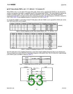
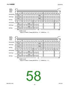
■ EXT Master Mode (PMPLL bit = “0”, M/S bit = “1”) (Audio I/F)
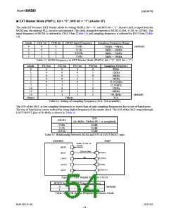
The audio I/F becomes EXT Master Mode by setting PMPLL bit = “0” and M/S bit = “1”. Master clock is input from the
MCKI pin, the internal PLL circuit is not operated. The clock required to operate is MCKI (256fs, 512fs, or 1024fs). The
input frequency of MCKI is selected by CM1-0 bits (Table 13) and sampling frequency is selected by FS3-0 bits (Table
14).
Mode
CM1 bit
CM0 bit
MCKI Input Frequency
Sampling Frequency Range
24kHz ∼ 48kHz
8kHz ∼ 24kHz
0
1
2
3
0
0
1
1
0
1
0
1
256fs
512fs
1024fs
256fs
(default)
8kHz ∼ 12kHz
8kHz ∼ 24kHz
Table 13. MCKI Frequency in EXT Master Mode (PMPLL bit = “0”, M/S bit = “1”)
Mode
0
1
2
3
FS3 bit
FS2 bit
FS1 bit
FS0 bit
Sampling Frequency
8kHz
0
0
0
0
0
0
1
1
1
0
0
0
0
1
1
0
0
1
0
0
1
1
0
1
1
1
1
0
1
0
1
1
1
0
1
1
12kHz
16kHz
24kHz
11.025kHz
22.05kHz
32kHz
48kHz
44.1kHz
N/A
5
7
10
11
15
Others
(default)
Others
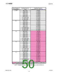
Table 14. Setting of Sampling Frequency (N/A: Not available)
The S/N of the DAC at low sampling frequencies is worse than at high sampling frequencies due to out-of-band noise.
The out-of-band noise can be reduced by using higher frequency of the master clock. The S/N of the DAC output through
LOUT/ROUT pins at fs=8kHz is shown in Table 15.
S/N
MCKI
(fs=8kHz, 20kHzLPF + A-weighted)
256fs
512fs
1024fs
82dB
82dB
92dB
Table 15. Relationship between MCKI and S/N of LOUT/ROUT pins
CODEC
DSP
256fs, 512fs, or
1024fs
MCKI
32fs or 64fs
1fs
BCLKx
BICK
SYNCx
LRCK
SDINx
SDTO
SDTI
SDOUTx
Figure 42. EXT Master Mode (x=1 to 4)
BCKO bit
BICK Output Frequency
0
1
32fs
64fs
(default)
Table 16. BICK Output Frequency in Master Mode
MS1402-E-06
2013/02
- 54 -

 AKM [ ASAHI KASEI MICROSYSTEMS ]