[AK4679]
■ CODEC System Clock (Audio I/F)
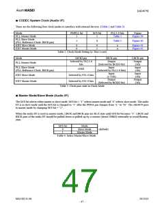
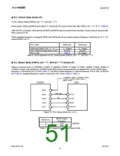
There are the following four clock modes to interface with external devices. (Table 2 and Table 3)
Mode
PMPLL bit
1
M/S bit
1
PLL3-0 bits
Table 5
Figure
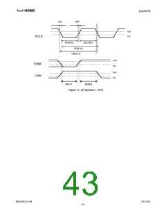
Figure 39
PLL Master Mode
PLL Slave Mode
(PLL Reference Clock: BICK pin)
EXT Slave Mode
EXT Master Mode
1
0
Table 5
Figure 40
0
0
0
1
x
x
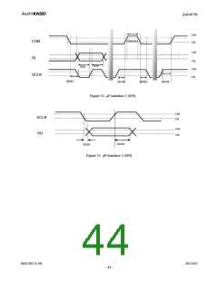
Figure 41
Figure 42
Table 2. Clock Mode Setting (x: Don’t care)
Mode
MCKI pin
Selected by PLL3-0
bits
BICK pin
Output
(Selected by BCKO bit)
Input
(Selected by PLL3-0 bits)
Input
(≥ 32fs)
Output
(Selected by BCKO bit)
LRCK pin
Output
(1fs)
Input
(1fs)
Input
(1fs)
Output
(1fs)
PLL Master Mode
PLL Slave Mode
(PLL Reference Clock: BICK pin)
GND
EXT Slave Mode
EXT Master Mode
Selected by FS1-0 bits
Selected by FS1-0 bits
Table 3. Clock pins state in Clock Mode
■ Master Mode/Slave Mode (Audio I/F)
The M/S bit selects either master or slave mode. M/S bit = “1” selects master mode and “0” selects slave mode. The audio
I/F is in slave mode until the M/S bit is changed to “1” after the PDNA pin changes from “L” to “H”. The AK4679 goes
to master mode by changing M/S bit = “1”.
When the audio I/F is used in master mode, LRCK and BICK pins are Hi-Z state until M/S bit becomes “1”. LRCK and
BICK pins of the audio I/F should be pulled-down or pulled-up by a resistor (about 100kΩ) externally to avoid floating
state.
M/S bit
Mode
0
1
Slave Mode
Master Mode
(default)
Table 4. Select Master/Slave Mode
MS1402-E-06
2013/02
- 47 -

 AKM [ ASAHI KASEI MICROSYSTEMS ]