[AK4679]
■ System Reset
Upon power-up, the PDNA and PDNE pis must be “L” and changed to “H” after all power supplies are supplied. The
period of “L” time more than 1.5μs is needed to reset the whole block of AK4679. All internal registers reset to their
initial values.
The ADC enters an initialization cycle when the PMADL or PMADR bit is changed from “0” to “1”. The initialization
cycle time is set by ADRST bit (Table 17). During the initialization cycle, the ADC digital data outputs of both channels
are forced to a 2's complement, “0”. The ADC output reflects the analog input signal after the initialization cycle is
complete. When using a digital microphone, the initialization cycle is the same as ADC’s.
Note 76. The initial data of ADC has offset data that depends on the condition of the microphone and the cut-off
frequency of HPF. If this offset is not small, make initialization cycle longer by setting ADRST bit = “0” or do
not use the initial data of ADC.
Digital Initialization Cycle
ADRST bit
fs = 8kHz
132.4ms
33.4ms
fs = 16kHz
66.2ms
16.7ms
fs = 44.1kHz
24ms
0
1
1059/fs
267/fs
(default)
6.1ms
Table 17. ADC Digital Initialization Cycle
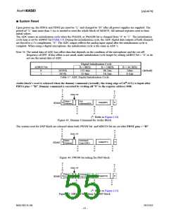
Audio block’s reset is released when the dummy command (Actually, the rising edge of 16th SCL) is input after
PDNA pins = “H”. Dummy command is executed by writing all “0” to the register address 00H.
S
T
A
R
T
S
T
O
P
R/W="0"
Slave *
Address
Sub
Address(00H)
S
Data(00H)
P
SDAA
N
A
C
K
N
A
C
K
N
A
C
K
(*: Refer to Figure 124)
Figure 43. Dummy Command for Audio Block
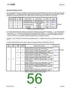
The system reset for DSP block are released when both PWSW bit and MRSTN bit are set after PDNE pins = “H”
S
T
A
R
T
S
T
O
P
R/W="0"
Slave
Address1
Command
Code (D0H)
S
Data(01H)
P
SDAE
A
C
K
A
C
K
A
C
K
Figure 44. PWSW bit setting for DSP block
S
T
A
R
T
S
T
O
P
R/W="0"
Slave
Address1
Command *
Code (D1H)
S
Data(01H)
P
SDAE
A
C
K
A
C
K
A
C
K
(*: Refer to Figure 125)
Figure 45. MRSTN bit setting for DSP block
MS1402-E-06
2013/02
- 55 -

 AKM [ ASAHI KASEI MICROSYSTEMS ]