[AK4675]
■ PLL Slave Mode (PMPLL bit = “1”, M/S bit = “0”)
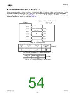
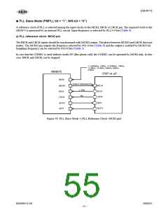
A reference clock of PLL is selected among the input clocks to the MCKI, BICK or LRCK pin. The required clock to the
AK4675 is generated by an internal PLL circuit. Input frequency is selected by PLL3-0 bits (Table 4).
a) PLL reference clock: MCKI pin
The BICK and LRCK inputs should be synchronized with MCKO output. The phase between MCKO and LRCK dose not
matter. The MCKO pin outputs the frequency selected by PS1-0 bits (Table 9) and the output is enabled by MCKO bit.
Sampling frequency can be selected by FS3-0 bits (Table 5).
In case that the CODEC is used without Audio I/F (like phone call), the CODEC can be operated by MCKI only. In this
case, BICK and LRCK can be stopped.
11.2896MHz, 12MHz, 12.288MHz, 13MHz,
13.5MHz, 19.2MHz, 24MHz, 26MHz,
27MHz
AK4675
DSP or μP
MCKI
256fs/128fs/64fs/32fs
MCLK
BCLK
LRCK
MCKO
BICK
≥ 32fs
1fs
LRCK
SDTI
SDTO
SDTI
SDTO
Figure 39. PLL Slave Mode 1 (PLL Reference Clock: MCKI pin)
MS0963-E-00
2008/05
- 55 -

 AKM [ ASAHI KASEI MICROSYSTEMS ]