[AK4675]
OPERATION OVERVIEW
■ System Clock (Audio I/F)
There are the following five clock modes to interface with external devices. (Table 1 and Table 2.)
Mode
PMPLL bit
1
M/S bit
1
PLL3-0 bits
See Table 4
Figure
Figure 38
PLL Master Mode (Note 78)
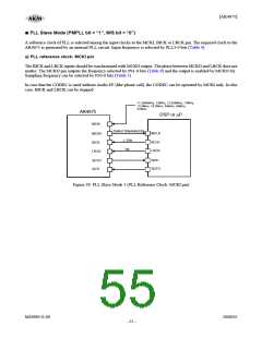
PLL Slave Mode 1
(PLL Reference Clock: MCKI pin)
PLL Slave Mode 2
(PLL Reference Clock: LRCK or BICK pin)
EXT Slave Mode
EXT Master Mode
1
1
0
0
See Table 4
See Table 4
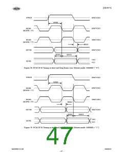
Figure 39
Figure 40
Figure 41
Figure 42
Figure 43
0
0
0
1
x
x
Note 78. If M/S bit = “1”, PMPLL bit = “0” and MCKO bit = “1” during the setting of PLL Master Mode, the invalid
clocks are output from MCKO pin when MCKO bit is “1”.
Table 1. Clock Mode Setting (x: Don’t care)
Mode
MCKO bit MCKO pin
MCKI pin
BICK pin
Output
(Selected by
BCKO bit)
LRCK pin
0
1
0
1
“L”
Selected by
PLL3-0 bits
Output
(1fs)
PLL Master Mode
Selected by
PS1-0 bits
“L”
Selected by
PS1-0 bits
Input
(≥ 32fs)
PLL Slave Mode
(PLL Reference Clock: MCKI pin)
Selected by
PLL3-0 bits
Input
(1fs)
Input
(Selected by
PLL3-0 bits)
Input
(≥ 32fs)
Output
PLL Slave Mode
(PLL Reference Clock: LRCK or BICK pin)
Input
(1fs)
0
0
0
“L”
“L”
“L”
GND
Selected by
FS1-0 bits
Input
(1fs)
EXT Slave Mode
EXT Master Mode
Selected by
FS1-0 bits
Output
(1fs)
(Selected by
BCKO bit)
Table 2. Clock pins state in Clock Mode
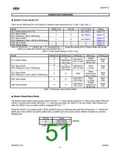
■ Master Mode/Slave Mode
The M/S bit selects either master or slave mode. M/S bit = “1” selects master mode and “0” selects slave mode. When the
AK4675 is power-down mode (PDN pin = “L”) and exits reset state, the AK4675 is in slave mode. After exiting reset
state, the AK4675 goes to master mode by changing M/S bit = “1”.
When the AK4675 is in master mode, LRCK and BICK pins are a floating state until M/S bit becomes “1”. LRCK and
BICK pins of the AK4675 should be pulled-down or pulled-up by the resistor (about 100kΩ) externally to avoid the
floating state.
M/S bit
Mode
0
1
Slave Mode
Master Mode
(default)
Table 3. Select Master/Slave Mode
MS0963-E-00
2008/05
- 51 -

 AKM [ ASAHI KASEI MICROSYSTEMS ]