[AK4675]
■ EXT Master Mode (PMPLL bit = “0”, M/S bit = “1”)
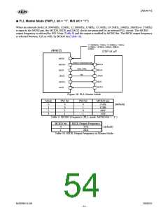
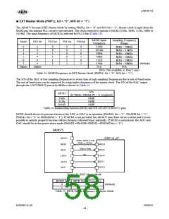
The AK4675 becomes EXT Master Mode by setting PMPLL bit = “0” and M/S bit = “1”. Master clock is input from the
MCKI pin, the internal PLL circuit is not operated. The clock required to operate is MCKI (256fs, 384fs, 512fs, 768fs or
1024fs). The input frequency of MCKI is selected by FS2-0 bits (Table 13).
MCKI Input
Frequency
Sampling Frequency
Range
Mode
FS3 bit
FS2 bit
FS1 bit
FS0 bit
x
x
x
x
x
x
0
1
4
5
6
7
0
0
1
1
1
1
0
0
0
0
1
1
0
1
0
1
0
1
256fs
1024fs
384fs
768fs
512fs
256fs
N/A
8kHz ∼ 48kHz
8kHz ∼ 13kHz
8kHz ∼ 48kHz
8kHz ∼ 26kHz
8kHz ∼ 26kHz
8kHz ∼ 48kHz
N/A
(default)
Others
Others
(N/A: Not available, x: Don’t care)
Table 13. MCKI Frequency at EXT Master Mode (PMPLL bit = “0”, M/S bit = “1”)
The S/N of the DAC at low sampling frequencies is worse than at high sampling frequencies due to out-of-band noise.
The out-of-band noise can be improved by using higher frequency of the master clock. The S/N of the DAC output
through the LOUT/ROUT pins at fs=8kHz is shown in Table 14.
S/N
MCKI
(fs=8kHz, 20kHzLPF + A-weighted)
256fs
512fs
1024fs
83dB
93dB
93dB
Table 14. Relationship between MCKI and S/N of LOUT1/ROUT1 pins
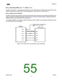
MCKI should always be present whenever the ADC or DAC is in operation (PMADL bit = “1”, PMADR bit = “1”,
PMDAL bit = “0” or PMDAR bit = “1”). If MCKI is not provided, the AK4675 may draw excess current and it is not
possible to operate properly because utilizes dynamic refreshed logic internally. If MCKI is not present, the ADC and
DAC should be in the power-down mode (PMADL=PMADR=PMDAL=PMDAR bits = “0”).
AK4675
MCKO
DSP or μP
256fs, 384fs, 512fs,
768fs or 1024fs
MCKI
BICK
LRCK
MCLK
BCLK
LRCK
32fs or 64fs
1fs
SDTI
SDTO
SDTI
SDTO
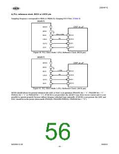
Figure 43. EXT Master Mode
BCKO bit
BICK Output Frequency
0
1
32fs
64fs
(default)
Table 15. BICK Output Frequency at Master Mode
MS0963-E-00
2008/05
- 58 -

 AKM [ ASAHI KASEI MICROSYSTEMS ]