ASAHI KASEI
[AK4115]
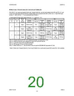
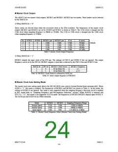
Block start, Channel status bit, User bit and Validity bit
The AK4115 can control and monitor block start, channel status bits, user bits and validity bit for RX and TX. B, C and
U pins are bi-directional and the direction of input/output can be selected by the BCU_IO bit. B, C, U and VOUT pins
become “L” (BCU_IO bit = “1”) in an unlocked state of Mode 2.
a. Serial mode & Except AES3 mode (P/SN pin = “L”, AES3 bit = “0”)
Block
Start
(B pin)
RX
TX
ASYNC BCU_IO
Channel
Status bit
Validity
bit
Channel
Status bit
Validity
bit
bit
bit
User bit
User bit
VOUT pin
VRX bit CT191-0 bits
(Note 24)
C pin
VIN pin
VTX bit
(Note 26)
0
Input
Output
Input
CR191-0 bits
N/A
U pin
N/A
U pin
(Note 25)
0
C pin
CR191-0 bits
(Note 23)
VRX bit
VOUT pin CT191-0 bits
(Note 24)
All
“0” data
(Note 27) (Note 26)
VIN pin
VTX bit
1
0
1
C pin
VRX bit CT191-0 bits
(Note 25)
VOUT pin
VRX bit CT191-0 bits
(Note 24)
VIN pin
VTX bit
(Note 26)
CR191-0 bits
U pin
1
C pin
CR191-0 bits
(Note 23)
All
“0” data
Output
U pin
VTX bit
Note 23. Channel status bit for RX can be monitored by both C pin and CR191-0 bits.
Note 24. Validity bit for RX can be monitored by both VOUT pin and VRX bit.
Note 25. C pin and CT191-0 bits are ORed internally.
Note 26. VIN pin and VTX bit are ORed internally.
Note 27. When UDIT bit is “1”, the recovered U bits are used for DIT(DIR-DIT loop mode of U bit).
Table 6. Block start, Channel Status bit, User bit and Validity bit in serial mode except AES3 mode (N/A: Not available)
MS0573-E-00
2006/12
- 20 -

 AKM [ ASAHI KASEI MICROSYSTEMS ]