ASAHI KASEI
[AK4115]
OPERATION OVERVIEW
Non-PCM (Dolby Digital, MPEG, etc) and DTS-CD Bitstream Detection
The AK4115 has a non-PCM bitstream auto-detection function, When the 32-bit mode Non-PCM preamble based on
Dolby “Dolby Digital Data Stream in IEC 60958 Interface” is detected, the NPCM bit sets to “1”. The 96-bit sync code
consists of 0x0000, 0x0000, 0x0000, 0x0000, 0xF872 and 0x4E1F. Detection of this pattern will set the NPCM bit to “1”.
Once the NPCM bit is set to “1”, it will remain “1” until 4096 frames pass through the chip without an additional sync
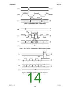
pattern being detected. When those preambles are detected, the burst preambles Pc (burst information: Figure 51) and Pd
(length code: Figure 52) that follow those sync codes are stored to registers. The AK4115 has also a DTS-CD bitstream
auto-detection function. When the AK4115 detects DTS-CD bitstream, the DTSCD bit sets to “1”. If the next sync code
does not occur within 4096frames, the DTSCD bit sets to “0” until no-PCM bitstream is detected again. The ORed value
of NPCM and DTSCD bits are output to AUTO bit. The AK4115 detects the 14-bit sync word and the 16-bit sync word
of a DTS-CD bitstream, the detection function can be set ON/OFF by DTS14 and DTS16 bits in serial mode. In parallel
mode, the logical OR value of the AUTO and DTS-CD bits are outputted to the INT1 pin. The DTS-CD bit detects both
the 14-bit sync word and the 16-bit sync word.
216kHz Clock Recovery
The integrated low jitter PLL has a wide lock range from 22kHz to 216kHz. The AK4115 has a sampling frequency
detection function (22.05kHz, 24kHz, 32kHz, 44.1kHz, 48kHz, 64kHz, 88.2kHz, 96kHz, 176.4kHz and 192kHz) that
uses either a clock comparison against the X’tal oscillator from the setting of XTL1-0, or the channel status information.
The PLL loses lock when the received sync interval is incorrect.
Reference Clock for PLL
The reference clock for the PLL can select the bi-phase signal or the clock supplied from the ELRCK pin. The bi-phase
signals are supplied to RX7-0 pins and the ELRCK pin is supplied to a sampled clock (1fs) from the word clock
(typically used by studio equipment). This is selected by the PSEL bit or the PSEL pin. PSEL bit and PSEL pin are ORed
internally.
PSEL
0
1
Reference Clock for PLL
RX Input
Default
ELRCK Input
Table 1. Setting of PLL Reference Clock
PLL Lock Time
The lock time at PSEL = “0” depends on sampling frequency (fs) and FAST bit (See Table 2). FAST bit is useful at lower
sampling frequency and is fixed to “1” in parallel mode. When PSEL is “1”, the lock time is 35ms (max) and is not
related to the setting of the FAST bit. The lock time in Table 2 does not include the power-up time of VCOM voltage.
Therefore, the power-up time of VCOM voltage must be added when PDN pin changes from “L” to “H”. The power-up
time of VCOM voltage is max. 15ms (Capacitor value of VCOM pin = 4.7 F).
µ
PSEL
FAST bit
PLL Lock Time
0
0
1
0
1
-
Default
≤ (20ms + 384/fs)
(20ms + 1/fs)
≤
≤ 35ms
Table 2. PLL Lock Time (fs: Sampling Frequency)
MS0573-E-00
2006/12
- 16 -

 AKM [ ASAHI KASEI MICROSYSTEMS ]