ASAHI KASEI
[AK4115]
1. Channel Status bit
1-1. RX
The data recovered from the bi-phase input signal is stored in CR191-0 bits. When the BCU_IO bit = “1”, the channel
status bits are available on the C pin according to the block signal timing. The channel status bits are outputted from
SDTO pin with audio data in AES3 mode.
1-2. TX
The channel status bit can controlled by the CT191-0 bits. When BCU_IO bit is “0”, the channel status bits are also
controlled by C pin. CT191-0 bits and the signal on the C pin are ORed internally.
The input to C pin is ignored in AES3 mode. When CTX bit is set to “0”, the channel status bits on DAUX pin are
outputted with audio data from TX. When CTX bit is set to “1”, the values of CT191-0 bits are outputted with audio data
from TX.
When the CCRE bit is “1” and AK4115 is in professional mode (bit0 = “1”), the CRC code can be generated according
to the professional mode definition in the AES3 standard. When the CCRE bit is “0”, the CRC data is not generated and
the data from the CT191-0 bits is passed to the TX directly. In the consumer mode (bit0 = “0”), the CRC code is not
generated.
In the consumer mode (bit0 = “0”), bits20-23(audio channel) must be controlled by the CT20 bit. When the CT20 bit is
“1”, the AK4115 corresponds to “stereo mode”, bits20-23 are set to “1000”(left channel) in sub-frame 1, and is set to
“0100”(right channel) in sub-frame 2. When the CT20 bit is “0”, bits20-23 is set to “0000” in both sub-frame 1 and
sub-frame 2.
All CR191-0 bits are transferred to CT191-0 bits when the CTRAN bit changes from “0” to “1”. The transferred
CT191-0 bits are valid after the next block start signal is detected. CTRAN bit goes to “0” after finishing the transfer.
Don’t write to the CT191-0 bits when the CTRAN bit = “1”.
2. User bit
2-1. RX
When the BCU_IO bit is “1”, the recovered user bit is available on the U pin according to block start timing. The user
bits are outputted from SDTO pin with audio data in AES3 mode.
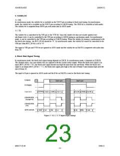
2-2. TX
When the BCU_IO bit is “0”, the user bit is sent to the U pin according to block start timing. When BCU_IO bit is “1”
and the ASYNC bit is “0”(synchronous mode), the user bit is controlled by the UDIT bit. When the UDIT bit is “0”, user
bit is set to “0”. When the UDIT bit is “1”, the recovered U bits are used for DIT( DIR-DIT loop mode of U bit). This
mode (UDIT bit = “1”) is enabled when the PLL is locked. The input to U pin is ignored in AES3 mode and the user bits
on DAUX pin are outputted with audio data from TX.
MS0573-E-00
2006/12
- 22 -

 AKM [ ASAHI KASEI MICROSYSTEMS ]