ASAHI KASEI
[AK4115]
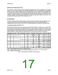
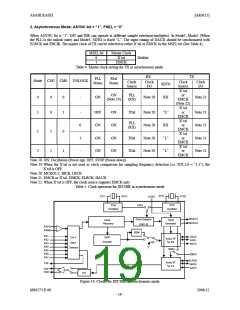
2. Asynchronous Mode: ASYNC bit = “1”, PSEL = “0”
When ASYNC bit is “1”, DIT and DIR can operate at different sample rates(non-multiples). In Mode1, Mode2 (When
the PLL is the unlock state) and Mode3, SDTO is fixed “L”. The input timing of DAUX should be synchronized with
ELRCK and EBCIK. The master clock of TX can be selected to either X’tal or EMCK by the MSEL bit (See Table 4).
MSEL bit
Master Clock
X’tal
0
1
Defalut
EMCK
Table 4. Master clock setting for TX in asynchronous mode.
RX
TX
PLL
Status
X'tal
Status
Mode CM1 CM0
UNLOCK
-
Clock
Source
Clock
I/O
Clock
Source
X’tal
or
EMCK
Clock
I/O
SDTO
RX
ON
(Note 19)
PLL
(RX)
0
1
0
0
0
1
ON
Note 20
Note 21
(Note 22)
X’tal
or
-
0
1
-
OFF
ON
ON
ON
ON
ON
ON
ON
X'tal
Note 20
Note 20
Note 20
Note 20
“L”
RX
“L”
“L”
Note 21
Note 21
Note 21
Note 21
EMCK
X’tal
or
EMCK
X’tal
or
EMCK
X’tal
or
PLL
(RX)
2
1
0
X'tal
X'tal
3
1
1
EMCK
Note 18. ON: Oscillation (Power-up), OFF: STOP (Power-down)
Note 19 When the X’tal is not used as clock comparison for sampling frequency detection (i.e. XTL1,0 = “1,1”), the
X’tal is OFF.
Note 20: MCKO1/2, BICK, LRCK
Note 21. EMCK or X’tal, EBICK, ELRCK, DAUX
Note 22. When X’tal is OFF, the clock source supports EMCK only.
Table 5. Clock operation for DIT/DIR in asynchronous mode
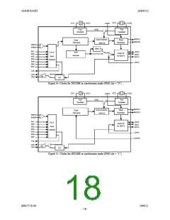
XTI2
XTI1
XTO1
XTO2
ACKS
X'tal
X'tal
XSEL
Oscillator
Oscillator
MCKO1
MCKO2
Clock Selector
(CM1-0)
Clock
Clock
Generator
Recovery
RXP0
RXN0
DEM
RX1
RX2
LRCK
BICK
8 to 3
DAIF
Audio I/F
for RX
Decoder
Input
RX3
RX4
SDTO
“L”
Selector
MSEL
RX5
RX6
RX7
EMCK
ELRCK
EBICK
DAUX
Audio I/F
for TX
TX0
TXP1
TXN1
DIT
Figure 16. Clocks for DIT/DIR in asynchronous mode
- 19 -
MS0573-E-00
2006/12

 AKM [ ASAHI KASEI MICROSYSTEMS ]