ASAHI KASEI
[AK4115]
Word Clock (Studio Sync Clock)
The word clock is used to synchronize clocks among studio equipment and is always synchronized to the sampling
frequency (1fs). The internal PLL generates MCLK, BICK and LRCK from the word clock supplied to the ELRCK pin.
The PLL lock range is 22kHz to 216kHz. The word clock (ELRCK pin) can receive signal levels of 0.5Vpp(min) when
AC coupled. In master mode, the clock phase between ELRCK pin and LRCK pin is within 5%. When the AK4115 is
±
supplied with a bi-phase signal and a word clock (ELRCK), the phase error between the LRCK and ELRCK is within
1/(128fs). Therefore, use LRCK and not ELRCK for the serial data output stream. When the word clock is not
±
synchronized to the bi-phase signal, WSYNC bit should be set to “0”.
DIT/DIR Mode
The AK4115 operates in either synchronous mode or asynchronous mode. In synchronous mode, transmitter and receiver
are operated by the same clock source. In asynchronous mode, transmitter and receiver are operated by different a
sampling frequencies that are selected by the ASYNC bit. Frequency multiples are not required in asynchronous mode.
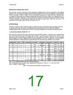
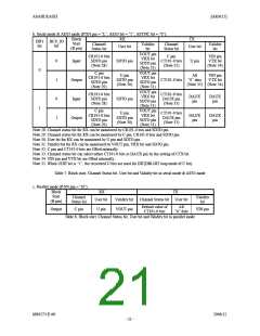
1. Synchronous Mode: ASYNC bit = “0”
PSEL and CM1-0 select the clock source and the data source for SDTO. In Mode 2, the clock source is switched from
PLL to X'tal when the PLL goes to the unlock state. In Mode 3, the clock source is fixed to X’tal, but PLL is also
operation and the recovered data such as channel status bit can be monitored. For Mode 2 and Mode 3, it is recommended
that the frequency of X’tal is different from the recovered frequency of the PLL. In Modes 4-6, the PLL source is
ELRCK and MCKO1/2, BICK and LRCK are generated by the PLL. The data source of SDTO is always DAUX.
Mode PSEL CM1
CM0 UNLOCK
PLL Status
ON
X'tal Status Clock source Clock I/O
SDTO
RX
ON
(Note 16)
ON
PLL
(RX)
X'tal
PLL
(RX)
X'tal
X’tal
0
1
0
0
0
0
0
1
-
-
Note 17
Note 17
Note 17
OFF
DAUX
RX
0
ON
ON
2
0
1
0
1
-
ON
ON
ON
ON
Note 17
Note 17
DAUX
DAUX
3
4
5
0
1
1
1
0
0
1
0
1
ON
(Note 16)
ON
PLL
(ELRCK)
X’tal
PLL
(ELRCK)
-
-
ON
OFF
ON
Note 17
Note 17
Note 17
Note 17
DAUX
DAUX
DAUX
DAUX
0
1
ON
ON
6
1
1
0
ON
X'tal
Note 15. ON: Oscillation (Power-up), OFF: STOP (Power-down)
Note 16: When the X’tal is not used as clock comparison for fs detection (i.e. XTL1,0= “1,1”), the X’tal is OFF.
Note 17. MCKO1/2, BICK, LRCK
Table 3. Clock operation for DIT/DIR in synchronous mode
MS0573-E-00
2006/12
- 17 -

 AKM [ ASAHI KASEI MICROSYSTEMS ]