ASAHI KASEI
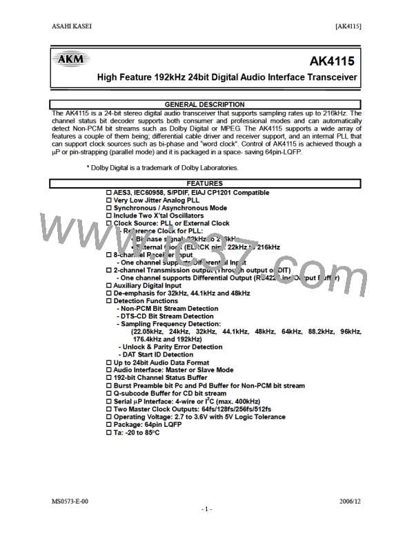
[AK4115]
Master Clock Output
The AK4115 has two master clock outputs, MCKO1 and MCKO2. MCKO2 has two modes. These modes can be selected
by the XMCK bit.
1) When XMCK bit = “0”
These clocks are derived from either the recovered clock or the X'tal oscillator. The frequencies of the master clock
outputs (MCKO1 and MCKO2) are set by OCKS0 and OCKS1 as shown in Table 9. The 512fs clock is changed into the
256fs clock when sampling frequency is 96kHz or 192kHz. The 512fs or 256fs clock is changed into the 128fs clock
when sampling frequency is 192kHz.
No. OCKS1 OCKS0 MCKO1 pin MCKO2 pin
X’tal
256fs
256fs
512fs
128fs
fs (max)
96 kHz
96 kHz
48 kHz
192 kHz
Default
0
1
2
3
0
0
1
1
0
1
0
1
256fs
256fs
512fs
128fs
256fs
128fs
256fs
64fs
Table 9. Master Clock Output Frequency
2) When XMCK bit = “1”
MCKO2 outputs the input clock of the XTI pin. The settings of CM1-0 and OCKS1-0 bits are ignored. The output
frequency can be set by the DIV bit. MCKO1 outputs a clock that is selected by the CM1-0 bits and OCKS1-0 bits.
XMCK bit DIV bit MCKO2 Clock Source
MCKO2 Frequency
1
1
0
1
X’tal (Note 36)
X’tal (Note 36)
x 1
x 1/2
Note 36. MCKO2 Clock Source is selected by XSEL bit.
Table 10. Select output frequency of MCKO2
Master Clock Auto Setting Mode
The master clock auto setting mode detects the MCLK/LRCK ratio (selects Normal/Double/Quad automatically). When
ACKS is “1”, this mode is enabled. The frequencies of MCKO1 and MCKO2 are shown in Table 11. In this mode, the
settings of OCKS1-0 are ignored. This mode is only supported when the sampling frequency detection circuit is enabled
in PLL mode.(refer to “Sampling Frequency and Pre-emphasis Detection” section.) When ELRCK is selected and
XTL1-0 = “11”, this mode is not supported. In X’tal mode, the frequencies of MCKO1/MCKO2 depend upon OCKS1-0.
The ACKS pin and ACKS bit are ORed internally.
Mode
MCKO1
512fs
256fs
MCKO2
256fs
128fs
64fs
Sampling Frequency Range
22kHz to 48kHz
Normal Speed
Double Speed
Quad Speed
64kHz to 96kHz
176.4kHz to 216kHz
128fs
Table 11. Master Clock Frequency Select (Master Clock Auto Setting Mode)
MS0573-E-00
2006/12
- 24 -

 AKM [ ASAHI KASEI MICROSYSTEMS ]