7
Operation
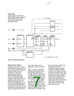
A block diagram of the HCTL-
20XX family is shown in Figure 6.
The operation of each major
function is described in the
following sections.
Figure 6. Simplified Logic Diagram.
Digital Noise Filter
input is tested for a stable level
being present for three
the counter. False counts
triggered by noise are avoided.
The digital noise filter section is
responsible for rejecting noise on
the incoming quadrature signals.
The input section uses two
techniques to implement
improved noise rejection.
Schmitt-trigger inputs and a
three-clock-cycle delay filter
combine to reject low level noise
and large, short duration noise
spikes that typically occur in
motor system applications. Both
common mode and differential
mode noise are rejected. The user
benefits from these techniques by
improved integrity of the data in
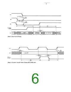
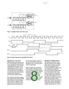
consecutive rising clock edges.
Therefore, the filtered output
waveforms can change only after
an input level has the same value
for three consecutive rising clock
edges. Refer to Figure 8 which
shows the timing diagram. The
result of this circuitry is that
short noise spikes between rising
clock edges are ignored and
pulses shorter than two clock
periods are rejected.
Figure 7 shows the simplified
schematic of the input section.
The signals are first passed
through a Schmitt trigger buffer
to address the problem of input
signals with slow rise times and
low level noise (approximately
< 1 V). The cleaned up signals
are then passed to a four-bit
delay filter. The signals on each
channel are sampled on rising
clock edges. A time history of the
signals is stored in the four-bit
shift register. Any change on the

 AGILENT [ AGILENT TECHNOLOGIES, LTD. ]