9
into account finite rise times of
the waveforms, asymmetry of the
waveforms, and noise. In the
presence of large amounts of
channels. Therefore, t (encoder
ity (i.e. 127. 2047, or 32,767
quadrature counts). Two’s-
complement arithmetic is
normally used to compute
position from these periodic
position updates. Three
modes can be used:
1. The IC can be put in 8-bit
mode by tying the SEL
line high, thus simplify-
ing IC interface. The
ES
state period) > t
. The
CLK
designer must account for
deviations from the nominal 90
degree phasing of input signals to
noise, t should be much greater
E
than 3t
to allow for the
guarantee that t > t
.
CLK
ES
CLK
interruption of the consecutive
level sampling by the three-bit
delay filter. It should be noted
that a change on the inputs that
is qualified by the filter will
internally propagate in a maxi-
mum of seven clock periods.
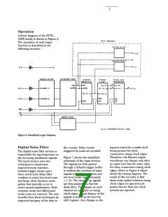
Position Counter
This section consists of a 12-bit
(HCTL-2000) or 16-bit (HCTL-
2016/2020) binary up/down
counter which counts on rising
clock edges as explained in the
Quadrature Decoder Section. All
12 or 16 bits of data are passed
to the position data latch. The
system can use this count data in
several ways:
outputs must then be
read at least once every
127 quadrature counts.
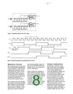
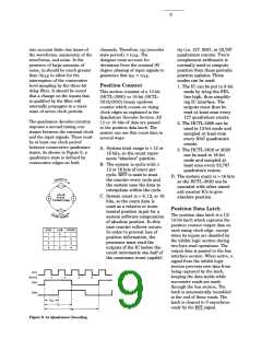
The quadrature decodercircuitry
imposes a second timing con-
straint between the external clock
and the input signals. There must
be at least one clock period
between consecutive quadrature
states. As shown in Figure 9, a
quadrature state is defined by
consecutive edges on both
2. The HCTL-2000 can be
used in 12-bit mode and
sampled at least once
every 2047 quadrature
counts.
3. The HCTL-2016 or 2020
can be used in 16-bit
mode and sampled at
least once every 32,767
quadrature counts.
A. System total range is ≤ 12 or
16 bits, so the count repre-
sents “absolute” position.
B. The system is cyclic with ≤
12 or 16 bits of count per
cycle. RST is used to reset
the counter every cycle and
the system uses the data to
interpolate within the cycle.
D. The system count is > 16 bits
so the HCTL-2020 can be
cascaded with other stand-
ard counter ICs to give
absolute position.
C. System count is > 8, 12, or 16
bits, so the count data is
used as a relative or incre-
mental position input for a
system software computation
of absolute position. In this
case counter rollover occurs.
In order to prevent loss of
position information, the
processor must read the
Position Data Latch
The position data latch is a 12/
16-bit latch which captures the
position counter output data on
each rising clock edge, except
when its inputs are disabled by
the inhibit logic section during
two-byte read operations. The
output data is passed to the bus
interface section. When active, a
signal from the inhibit logic
section prevents new data from
being captured by the latch,
keeping the data stable while
successive reads are made
outputs of the IC before the
count increments one-half of
the maximum count capabil-
through the bus section. The
latch is automatically reenabled
at the end of these reads. The
latch is cleared to 0 asynchron-
ously by the RST signal.
Figure 9. 4x Quadrature Decoding.

 AGILENT [ AGILENT TECHNOLOGIES, LTD. ]